Hey! This site is reader-supported and we earn commissions if you purchase products from retailers after clicking on a link from our site.
5/3, or 4/3 air valves, like the 5/2 and 4/2 air valves, are used to power double-acting air actuators. These actuators could be air cylinders, rotary actuators, or any air-driven device that requires air to be supplied to alternate ports in order for the device to cycle.
This article will provide all the relevant information on the 5-way 3-position pneumatic solenoid valves necessary, to help you gain a better understanding of them!
Table of Contents
- What Is a 5/3 Directional Control Valve?
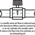
- What Is a 3-Way Pneumatic Valve?
- Where to Buy 5/3 Pneumatic Solenoid Valves Online
- FAQs (Frequently Asked Questions)
- Reader Questions & Responses
What Is a 5/3 Directional Control Valve?
The 5/3 solenoid valve, or 4/3 series, is a directional-control valve. The 5/3 valve and 4/3 valve body designs allow compressed air to flow to one port of a double-acting air actuator while simultaneously allowing air to exhaust from the other port on the same air actuator at the same time.
By shifting the internal flow paths of the valve, the 5/3 and 4/3 air valve sends compressed air alternatively to each of the two actuator ports and exhaust from the other, thus allowing the double-acting air cylinder to function.
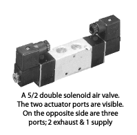
The valve shown in the following image has 5 airports. It may be a 5/3, or it may be a 5/2 configuration. You cannot tell the difference from looking at the valve body. The valve schematic, which is typically shown on the side of the valve, is the only way you can determine if the spool is two-position (a 5/2) or three-position, (a 5/3 solenoid valve) unless it is identified as such by the vendor.
What Is a 3-Way Pneumatic Valve?
The “extra” position inside a 5/3 way valve or 4/3 air valve means that the internal spool can be shifted to a center position. The typical spool movement is end-to-end inside the valve. With a two-position valve, the spool shifts from the end, across the middle, and to the other end. In the three-position body style, the spool can be positioned to stop in the middle location to accomplish a specific goal.
Each of the three spool positions is selected to accomplish the desired result in the action of the air cylinder.
Since valves with three-position spools are more expensive than their two-position counterparts, the selection of a three-position valve will be deliberate. The circuit designer will have a particular scenario in mind for the action of the air cylinder when the valve that controls it is shifted, and that circuit will require the selection of a specific three-position valve to accomplish the goal.
A 5/3 way valve or 4/3 valve will normally have two internal spring actuators that, when the valve is not being operated by an external valve actuator, shift that valve spool to the center position automatically. It is normally when the 5/3 or 4/3 valve is “at rest” that the third of the three positions come into play. Learn more about actuators here!
5/3 Way Valve vs 4/3 Way Valve Configuration
- The 5/3 valve body ports are; one supply port, two air cylinders ports, and two exhaust ports.
- The 4/3 valve body ports are; one supply port, two air cylinder ports, and one exhaust port.
The first number in a valve designation will identify the number of working ports that the valve has. Therefore, the 5/3 or 4/3 air valve will have either five or four working ports, respectively.
The second digit in the valve designation indicates how many positions that valve can have. The 5/3 or 4/3 will have three positions.
Center Position Configuration
In that third, otherwise known as the center position, three things can happen to the airflow through that particular valve, these are known:
- Blocked Center
- Open Center
- Pressure Center
Let’s gain a better understanding of the three!
Blocked Center
In this position, all the valve ports are blocked. Air cannot flow through the valve to either actuator port as the supply path to those ports is closed.
Air also cannot flow from either actuator port to either exhaust port as those flow paths are blocked. The supply, actuator, and exhaust ports are all closed.
In this position, since air cannot travel through the valve to the air cylinder or from the cylinder back through the valve, then when the valve shifts into “Blocked Center”, the air cylinder will freeze.
That is the intent of the circuit designer when selecting a “Blocked Center” 5/3 or 4/3 valve. When this valve is “at rest”, they want the cylinder to be frozen. Air cannot get in or out of the cylinder, and it stops dead.
Open Center
When the 5/3 or 4/3 air valve is shifted into its central position in an “Open Center” three-position style valve, the supply line to the valve is blocked, and both cylinder ports are open through the valve to the exhaust.
With this spool selection, the circuit designer has decided that when the valve is “at rest”, it will be necessary to move the cylinder rod (and of course the end of rod tooling) by hand, or perhaps another operation will move the rod and tooling, and since there is no air on either side of the piston inside the cylinder, this can happen relatively easily, this is facilitated.
Pressure Center
In the “Pressure Center” position, air will flow from the supply to both air actuator ports, and the exhaust port(s) are blocked. In this scenario, the air circuit designer wants air on both sides of the air actuator when this valve is at rest. The air actuator might be a rodded air cylinder, but it also might be a rodless type.
By exerting pressure on both sides of the piston inside a rodless ( band, magnetically couples, or cable type) cylinder, the end of rod tooling can be held in one location. As an added advantage, if there are small leaks in the lines or through the seals of the rodless cylinder, a pressure center valve means that the air pressure will be maintained inside the cylinder regardless of small leaks.
Not all valve manufacturing companies offer three-position valves, and for those that do, not all offer all three possible valve spool configurations.
Where to Buy 5/3 Pneumatic Solenoid Valves Online
A 5/3 pneumatic solenoid valve is readily available online in a variety of places. First of all, I have picked out the following two examples on Amazon.

- Product Name : Pneumatic Solenoid Valve; Model : 4V230C-08; Operation Type : Internally Piloted Acting Type
Prices pulled from the Amazon Product Advertising API on:
Product prices and availability are accurate as of the date/time indicated and are subject to change. Any price and availability information displayed on [relevant Amazon Site(s), as applicable] at the time of purchase will apply to the purchase of this product.

- 【Sealing Thread Design】Our pneumatic Plunger valve adopts high-quality and high-precision sealed threaded female interface to ensure excellent air tightness and extend service life
Prices pulled from the Amazon Product Advertising API on:
Product prices and availability are accurate as of the date/time indicated and are subject to change. Any price and availability information displayed on [relevant Amazon Site(s), as applicable] at the time of purchase will apply to the purchase of this product.
Other places you can begin your search are reputable stores including:
Apart from online retailers, you can visit local hardware retailers and seek their advice. If they don’t have the valves in stock, I’m sure they’ll be able to help and potentially order one for you!
FAQs (Frequently Asked Questions)
A 5 3 valve is a directional-control valve that has one supply port, two air cylinders port, and two exhaust ports. The 3 represents the three-position body style, where the spool can be positioned to stop in the middle location to accomplish a specific goal as well as going end to end.
A 5-port valve stays true to its name, it’s a valve that contains 5 ports. One port is for the air supply, two ports are to connect to air cylinders and the remaining 2 ports act as exhausts.
The key difference between a 3 2 solenoid valve and a 5 2 solenoid valve is that the 5 2 valve has an additional air cylinder and exhaust port. 3 2 solenoid valves typically contain a supply port, air cylinder port, and exhaust port, while a 5 2 valve contains a supply port, two air cylinder ports, and two exhaust ports.
A 5-way solenoid valve, also known as a 5-way directional control valve, is a valve used to send compressed air alternatively to each of the two actuator ports of a double-acting air cylinder and its exhaust ports from, and so, by alternating it allows the double-acting air cylinder to function.
Additional valve reading:
- Types of Compressed Air Valves – Guide To Pneumatic Valves
- Pneumatic Flow Control Valves – What Are They, How Do They Work?
- Air Compressor Air Line Non-Return valves/Inline (In The Air Line) Air Check Valves Explained
- Check Valve Sizes
- What is Check Valve Cracking Pressure
- Air Compressor Troubleshooting Check Valve
- Air Compressor Unloader Valve Explained
- Unloader Valves On Twin V Piston Compressor Guide
- 5-2 Air Valves
- 4-2 Compressed Air Valves
- 3-2 Air Valves
- Drawing a 5/3 compressed air valve
- Draw A 5/2 Air Valve
- Pneumatic Soft Start Valves
- Solenoid Pilot Air Valves
- Compressed Air Solenoid Valve Guide
- Air Compressor Auto Drain Valves Guide
- Needle Valve vs Ball Valve
- Globe Valve vs Ball Valve
- Globe Valve vs Gate Valve
- Butterfly Valve vs Gate Valve
Reader Questions & Responses
5/3 Closed Centre Valve Default Position
Question
We use a Festo 170248 5/3 closed center valve to actuate a double-acting cylinder.
I understand that if the air or electrical supply is interrupted the cylinder will remain in position (except for some creep due to the different surface area at each end.
My question is if the valve function itself fails (spring/leak etc.) do these valves default to the center closed position?
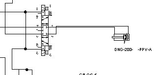
We are trying to answer a safety question as to what happens if something goes wrong with the valve. Thanks. I’ve attached the schematic, the valve in question is the one going to the DNG-200 cylinder.
Response
I spent some time working as a territory rep for Festo, so know that if you contact them, they will have a distributor rep by to see you in no time, at least that’s the way it used to be.
Having said that, the best thing to do to determine the answer to your question is to look at the schematic of the valve.
I have uploaded a copy of the Festo 170248 5/3 closed center valve schematic, and ask you to review it. In particular, look at either end of the schematic, and note the graphic that denotes a spring.
Since there is a spring on either end, if this valve fails due to loss of electricity or air pressure, it is designed to “spring center”, and in so doing, block all ports.
If there were no springs, “sticktion” would come into play, and the valve spool would likely stay in the position it was last in if the power and air disappeared unless vibration moved the spool. That would not be a safe type of valve configuration to use.
In other words, the valve you have selected is designed to be “fail-safe” by blocking all ports and stopping any actuators in the event of a power or air disruption.
Hope that helps.
Questioner
Hi Bill,
Thanks for the response. Festo seems to concur with what you say.
I spoke to them and got a couple of varying answers. They obviously don’t want to commit but the 1st guy said: that with no electrical power it center closes, with no air its center closes, and with a broken spring it will still center since the springs are designed not to go past the center.
The 2nd guy agreed with the 1st but was less committed in his response and said they couldn’t say how far the spool might move with 1 spring failing due to variable friction etc. which I can also understand. I think it depends a bit on who you talk to.
So overall it looks like we are OK. The rub will come in the safety review when we talk about failure modes, and whether any redundancy needs to be built into the system. I’ve seen double pilot valves for presses, lots of bucks, and probably overkill. However, the user does have his hand under this ram a lot of the time so we’ll see.
We are having a Festo rep come in to take a look also.
Thanks again, great website by the way. v. useful.
Response
Thanks for the comment about my website. I’m sure glad you find it useful.
With personal safety, the question is, how far do you go?
The valve is supposed to work. If a spring fails, it may or may not.
In order to take that out of the equation, then plumb in double redundancy so that if one valve fails, the other valve will do the job.
The odds of both valves or valve components failing at the time of power or compressed air outage are probably more remote than you winning the power ball lottery.
Is that safe enough? That’s up to the safety committee.
Festo is a first-class company selling extremely well-built air components. But even at that, they cannot determine the conditions of use or how a product will ultimately fail, and the ramifications of that. That’s up to the user.
Again, thanks for your kind comments.
B.
Response
I don’t know your exact application, but perhaps some sort of pusher could be made/used to keep the operator’s hand completely out of the potential danger area.
Response
Good thought, Doug. The device in question is actually called an “anti-tie down” and its purpose is to ensure that an operator’s hands are not ever in an area where they could be impacted upon.
B.
Questioner
Just a follow-up on this, the only thing I can see that will give that redundancy is something like one of the Ross safety valves which are usually used for presses.
These are designed to return the cylinder to a safe or retracted position if one spool doesn’t move as expected. This seems overkill for us, I’d like to find a compromise. The problem is detecting the fault once it occurs.
Response
A pressure sensor can tell a system if a particular valve has shifted or not, which can be tied into a blocking check valve that locks a cylinder if necessary.
There are lots of folks in the industrial pneumatic distributor business that can help you design the appropriate circuit and specify the products you need.
Circuit design is out of the purview of this site. If you want some help with that send me a message through the contact page and I’ll provide rates.
If you have any questions regarding a 5/3 directional control valve, please leave a comment below, with a photo if applicable, so that someone can help you!