Drawing a 5-3 air valve can be a bit tricky. If you haven’t already done so, please take a few minutes to look at the other pages on this site about drawing air valve schematics, starting with drawing the 2-2 air valve. The 2-2 is the easiest to draw and lays the foundation for how to draw a 5/3 compressed air valve.
The purpose of a valve schematic is to show all of the possible positions for that one air valve.
This allows the system designer to insert a particular valve into an air circuit diagram, to show system builders what valves to acquire, and the condition of that valve so it can be installed in the circuit in the position necessary when the circuit is shut down.
The completed circuit schematic will also show all the valve actuators necessary for each air valve in that circuit, for the circuit to operate as designed.
On the page “drawing the 5/2 air valve”, the final schematic for the 5/2 was as shown in Fig. 53.
Fig. 53 shows both positions of this 5/2 valve and the corresponding flow paths, depending on that valve position. You can see how the flow paths change whether it is the right side or the left side of the valve that is currently in control.
The first number in a valve designation, in this case a five, indicates that this valve will have five ports. The second number indicates the number of positions for that valve, so a 5/3 valve will have three positions, not two as shown in Fig. 53.
Where and how does that third position get drawn? Please see Fig. 55, below.

In drawing the three position valve schematic, we essentially split the 5/2 valve schematic in half. We add a space in the center. This is where we will show the flow paths available for the third position possible with the 5-3 (also known as 5/3) valve.
The third position in a 5/3 valve is a center position. The air control mechanism inside 5/3 valve (usually a spool of some sort) is shifted into the center position inside the valve by one of the two internal spring actuators normally located inside the valve at each end of the internal spool. These springs center the spool into the valves third position, again typically when the valve is at rest.
The internal valve spool might have – O – rings installed on it. It might have a bonded Buna-rubber surface. It might be all aluminum or plastic and slide back and forth inside a tube packed with “O” ring type seals in the tube and not on the spool, or it might be a high tolerance, machined metal-to-metal spool.
All of these varieties of valve spools are available from the major valve manufacturers around the world.
Each spool style have their benefits and their negatives and knowing them will help you choose the valve technology that best suits the application. Much information about each valve type will be available from that manufacturer’s website, and a prudent valve buyer will take the time to research on those sites.
Central Position Offers Three Valve Functions
The third position in a three position valve can offer the circuit designer one of the following options for air control:
- A Blocked Center
- An Open Center
- A Pressure Center
These three possible central-position flow configuration are note available from all valve manufacturers. If you are looking for a specific 5/3 valve function, you may have to shop around to find the source that makes that version.
In order to complete the schematic for our 5/3 compressed air valve, we have to determine which of these three configurations we need for our valve, and insert the schematic for that flow path between the other two positions.
Here are the schematics for the three positions:


Fig. 60 shows the valve schematic for a 5 ported, three position, Blocked Center, compressed air valve.
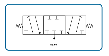
I have shown the two internal spring actuators on this schematic which, when any external valve actuators are not being employed and the valve is at rest, these spring will center the spool in the valve, selecting the center position by default.
Since, at rest, this valve will be in its center position and the center position will be “in control”, the air supply – typically depicted by the black circle and a line leading up to the supply port of the valve body – is shown in the center position.
If this 5/3 were left in an energized state, that is to say – that the external valve actuators were solenoids and this valve was at rest with one of the solenoids actuated, then the valve would be shifted to one side or the other, and the schematic for that valve would so depict this.
In using the Blocked Center 5/3 valve diagram, the circuit designer has decided that when this valve is at rest the all ports will be shut. No air can flow into the valve, and no air can flow from the two cylinder ports at the top of the valve into or out of the air actuator.
Note: if the blocked center 5/3 valve is selected to try to freeze the piston inside a normal, rodded air cylinder, over time, the piston and rod will tend to creep a little due to piston surface area imbalance. One side of the piston in a typical air cylinder has a piston rod in the center of it reducing surface area upon which the compressed air can push allowing the slightly greater force on the side of the piston without the rod to drive the piston off position, and the cylinder piston will tend to “creep” towards the end with the rod.
Force = pressure x area. If the surface area on either side of the piston were exactly the same, the piston would be frozen in position by a 5/3 blocked center valve.
In Fig. 61, we show the same type of schematic, but now the center position shows the Open Center flow path.

Compressed air circuit designers will typically use an open center 5/3 valve where there is a need to move the rod and/or rod tooling when the valve is at rest. With both cylinder ports on the valve open to atmosphere, and with the compressed air supply blocked, then the rod and the tooling can be moved easily by hand.
Or, in the event that the valve is solenoid operated, and there is a power failure, the air would dump from the cylinder from both air ports, and the tooling could be moved manually back to a safe-start position.
The last 5/3 air valve configuration is Pressure Center.
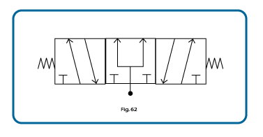
Using this valve configuration, the circuit designer has decided that, when this valve is at rest, compressed air will be supplied to both ports on the actuator at the same time.
This will stop cylinder rod travel. Although, if it is a typical rodded type air cylinder, the piston surface area imbalance will allow the cylinder piston to creep.
If the air actuator is a rodless cylinder, or a double rod air cylinder, or perhaps a rotary actuator – all of which have comparable surface areas on both sides of their pistons – then the pressure center position would freeze them solid.
In the event there were air leaks between the valve and the actuator, that the air supply to the actuator through the valve was constantly regenerated, leaks which could cause the piston to shift one way or the other, would be overcome.
I recall one application for a 5/3 pressure center, lever operated hand valve. This client was opening a swinging door on a dump bin, and the three position valve was used to manually extend or retract the cylinder that controlled the door opening. By shifting the valve one way the cylinder would open the door. By using the valve actuator lever to shift the valve the other way, the cylinder would close the door to reduce, and ultimately stop, the flow. By letting go of the valve actuator lever, the valve – in its center position – would feed air to both sides of the door cylinder, holding the door in place. That, over time, the imbalance in piston surface area would allow the piston to move, did not really affect this operation as they simply operated the valve lever to adjust the door position again as required.
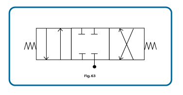
By now I expect that you’ll have figured out that exactly the same process is used to draw the 4/3 valve. Fig. 63 shows a 4/3 valve with blocked center position. You would simply substitute the schematics for the open center or pressure center as needed, to show all configurations of the 4/3 air valve.
The 4/3 air valve body has only one exhaust port as opposed to two, as shown in the next image.
Additional valve reading:
- Types of Compressed Air Valves – Guide To Pneumatic Valves
- Pneumatic Flow Control Valves – What Are They, How Do They Work?
- Air Compressor Air Line Non-Return valves/Inline (In The Air Line) Air Check Valves Explained
- Check Valve Sizes
- What is Check Valve Cracking Pressure
- Air Compressor Troubleshooting Check Valve
- Air Compressor Unloader Valve Explained
- Unloader Valves On Twin V Piston Compressor Guide
- 5 3 Valves Explained
- 5-2 Air Valves
- 4-2 Compressed Air Valves
- 3-2 Air Valves
- Draw A 5/2 Air Valve
- Pneumatic Soft Start Valves
- Solenoid Pilot Air Valves
- Compressed Air Solenoid Valve Guide
- Air Compressor Auto Drain Valves Guide
- Needle Valve vs Ball Valve
- Globe Valve vs Ball Valve
- Globe Valve vs Gate Valve
- Butterfly Valve vs Gate Valve