In most pneumatic power circuits, flow control valves are implemented and used to control the direction, rate, and pressure within the system’s line. There are a variety of different valves that offer different aspects of control, and so, this article will provide you with all the relevant information on pneumatic flow control valves and their purposes.
Table of Contents
- What Are Pneumatic Flow Control Valves?
- How Do Flow Control Valves Work?
- Types of Flow Control Valves
- Choosing the Right Flow Control Valve
- FAQs (Frequently Asked Questions)
What Are Pneumatic Flow Control Valves?
A flow control valve’s main purpose in pneumatic systems is to regulate the pressure or flow of air. Some valves are able to regulate flow while still allowing it to pass through another section while other types are designed to simply allow the flow to pass, stop or switch its direction.
Traditional flow valves have an aperture that is designed to change, which allows the flow rate to be increased or decreased.
In terms of compressed air, flow controls are devices that are used when you need to control the speed of an air cylinder, a pneumatic rotary actuator, or any other air-driven device that has an IN port and an OUT port.
Depending on the type of flow control used in an air circuit, flow controls can control the speed of actuators on either the extend stroke, the retract stroke, or in both directions. Flow control valves can be used to reduce the rate of flow in a specific section, which then results in a slower actuator speed.
They are designed so that air flows in one direction, which allows free flow in the opposite direction. There are different types of flow control valves, however, and they all serve their own purpose. I’ll dive into the types further down the page!
It’s important to not confuse flow control valves with pressure controllers, or regulators. Whilst there is a relationship between pressure and flow, it is not necessarily linear, and using a pressure regulator to control flow could result in a lot of wasted energy, as well as potential component damage.
How Do Flow Control Valves Work?
Though there are different types of flow control valves available, they all work on the same basic principle. The smaller the hole, or orifice in a pipe, the lower the rate of flow of air at any given pressure.
Control valves often have a finely machined stem that matches the profile of the valve’s seat. When fully closed, they will be no airflow allowed through the valve. As the valve is progressively opened, more and more air is allowed to flow through the valve, until when the valve is fully opened and the flow is at its maximum.
Flow control valves can be either bi-directional, which allows them to control flow in either direction or uni-directional, where the flow can only be controlled in one direction only – usually the component or exhaust side. Uni-directional vales will often have a check valve device allowing full airflow in the opposite direction to ensure directional control.
Flow is directly proportional to speed and pressure is directly proportional to strength. Therefore, if you increase the pressure, you are going to increase the strength available, and if you increase the flow into an actuator, you will be increasing the speed.
Essentially, the flow will change the speed of an actuator while the pressure will change the force of the actuator. The valve’s position itself will depict which direction the actuator is in. Flow control valves work by requiring a pressure differential between upstream and downstream pressure.
As mentioned, uni-directional control valves are often connected to the exiting pressure from the exhaust, causing the air pressure to expel through a connection hose at a reduced rate.
The air, therefore, doesn’t directly exhaust and instead travels through the valve at an increased resistance before being expelled slowly. When adjusting the flow control valve, it’s easy to notice that it controls the existing exhaust rate and the extracting speed of the bore.
The control valves here essentially control and reduce the amount of exhaust that is being expelled. The air normally would travel through the exhaust, but here the path of resistance only allows travel in one direction directly through at full pressure. When the air pressure travels in the opposite direction through a path of increased resistance, it will get proportionally controlled by the flow control valve.
Types of Flow Control Valves
Cylinder flow controls come in all shapes and sizes. Some are designed to be inline between the valve and the cylinder port. Others are built to screw right into the cylinder port. Some come with their own quick fittings already installed.
Other cylinder flow controls screw into the exhaust ports of the air valve instead of the air cylinder ports. Be cautious with valve exhaust flow controls. If the air valve is a 4 ported x 2 way it has only one common exhaust for both cylinder ports.
Therefore, an exhaust flow control installed in the single exhaust port will control the speed of the cylinder, and provide the same rod speed, in both extension and retraction. If this doesn’t suit the application, you will need to select a different form of flow control.
Another issue with valve exhaust port flow controls is if the airline from the cylinder to the valve is long, it is possible that the cylinder will have already completed its stroke before the exhaust cylinder flow control will have had time to throttle the exhaust flow of air and slow the cylinder.
Let’s take a look at some of the different types of control valves available:
- Traditional control valves
- Ball valves
- Butterfly valves
- Gate valves
- Globe valves
- Needle control valves
Traditional Control Valves
Traditional control valves are the most basic type of flow control and they’re typically limited to fully open or fully closed positions. They are of a very simple design and capabilities. Changing directional flow, or pressure during system operation would require a complex hydraulic circuit.
Each desired direction, flow, or even pressure would need an individual traditional valve in order to control it. Directional control valves would be a step up from these traditional valves, as they will allow fluid into different path directions, from one or more sources.
Traditional control valves essentially control the stop, start, and change in direction of flow of a medium.
Ball Valves
These types of flow control valves have a perforated, hollow, and pivoting ball that is used to control the flow going through the valve. The hole of the ball is open when it aligns with the flow of medium heading through the valve, pivoted typically by a 90-degree turn.
Ball valves are very reliable and durable, even after very lengthy usage. These valves are strictly open/close valves, and shouldn’t be used to regulate flow.

- Body & Ball Type:Full Port, Low Operation Torque,316 Stainless Steel
Prices pulled from the Amazon Product Advertising API on:
Product prices and availability are accurate as of the date/time indicated and are subject to change. Any price and availability information displayed on [relevant Amazon Site(s), as applicable] at the time of purchase will apply to the purchase of this product.
Butterfly Valves
Butterfly valves are primarily used for either regulating or isolating flow in a system. They do, however, have a similar principle to ball valves, in that they’re designed for quick shut-off of flow if necessary.
These types of valves have a disk located within its center and a rod connected to an actuator which is passed through the disk. The disk is always present within the flow of butterfly valves, meaning that a pressure drop is always induced in the flow, irrespective of the positioning. Therefore, this pressure drop must be accounted for!
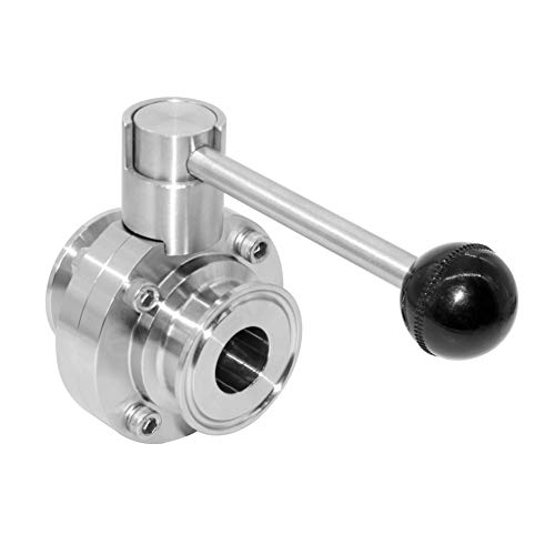
- Body material:Stainless Steel 304.
Prices pulled from the Amazon Product Advertising API on:
Product prices and availability are accurate as of the date/time indicated and are subject to change. Any price and availability information displayed on [relevant Amazon Site(s), as applicable] at the time of purchase will apply to the purchase of this product.
Gate Valves
Gate valves are linear motion valves that are best suited to shutoff applications, especially emergencies as they’re so quick and easy to close. These types of valves utilize a wedge-like disc which helps to isolate the flow of the medium and can provide a very tight seal!
The gate’s operation is perpendicular to the medium, the gate moves upwards to open the valve or downwards to close the valve and create a seal with the seats. Gate valves cannot be used to regulate flow because if they’re left in a partially open position they’re very prone to eroding, which will damage the valve, leading to a shorter lifespan.

- Made with High Quality ProGuard PVC II material
Prices pulled from the Amazon Product Advertising API on:
Product prices and availability are accurate as of the date/time indicated and are subject to change. Any price and availability information displayed on [relevant Amazon Site(s), as applicable] at the time of purchase will apply to the purchase of this product.
Globe Valve
Globe valves are designed to regulate the flow of air in a pipeline. Globe valves have a stationary ring seat and a disk-type element referred to as a plug. Their name is typically down to the face they resemble a globe, a spherical body shape.
Globe valves have two halves to their body which are separated by an internal baffle. and they’re best suited to applications that require frequent operation and throttling, they’re always reverse seated.

- Compression Style Stop Valve Ideal for Stopping, Starting, and Regulating Fluid Flow in Pipelines
Prices pulled from the Amazon Product Advertising API on:
Product prices and availability are accurate as of the date/time indicated and are subject to change. Any price and availability information displayed on [relevant Amazon Site(s), as applicable] at the time of purchase will apply to the purchase of this product.
Needle Control Valves
Needle control valves are variable control valves that are not compensated by pressure. In these valves, the medium will be forced to make two ninety-degree turns, and there is a needle in the middle of the valve, in the way of the medium. The needle helps to create a pressure differential between the upstream and downstream.
By adjusting the depth of the needle, you can change the flow rate of the medium coming through the valve by controlling the size of the orifice, allowing more or less flow through the valve.
One downfall of a needle valve is that they restrict flow rate in both directions. Using a needle valve for speed control of a piston air cylinder in forward motion will restrict the motion on the return stroke.

- ★Needle valve is an important part of the instrument measurement pipeline system, used to adjust the flow to the instrument or other industrial applications, open or cut off the pipeline path
Prices pulled from the Amazon Product Advertising API on:
Product prices and availability are accurate as of the date/time indicated and are subject to change. Any price and availability information displayed on [relevant Amazon Site(s), as applicable] at the time of purchase will apply to the purchase of this product.
For more detailed information, and comparisons on the types of flow control valves, please visit the following articles:
- Needle Valve vs Ball Valve – Differences, Design, Mechanisms, Applications & More
- Globe Valve vs Ball Valve – Differences, Design, Mechanisms, Applications & More
- Globe Valve vs Gate Valve – Differences, Design, Mechanisms, Applications & More
- Butterfly Valve vs Gate Valve – Differences, Design, Mechanisms, Applications & More
Choosing the Right Flow Control Valve
I recommend that you do not purchase a needle valve to try and provide speed control for an air cylinder. Yes, a needle valve will work somewhat in controlling the speed of an air cylinder but, it is not your best option as it may create more problems than it solves in your air circuit.
Needle valves control the flow of air both into and out of the air cylinder. The compressed air flows through the needle at the same speed regardless of the direction of airflow. And therein lies part of the problem with using needle valves to try and control cylinder speed.

In order to get the cylinder speed slowed to your desired cycle rate by throttling the exhaust with a needle valve since compressed air has to follow that same path when the cylinder reverses, you now have throttled the inrush of compressed air into the cylinder too.
In larger bore air cylinders the compressed air flowing into the cylinder through a needle valve can be severely limited. The restricted inrush of compressed air may not be fast enough for that air cylinder to be able to build up sufficient force inside the air cylinder to start to move the piston smoothly.
With restricted compressed air inrush due to the needle valve throttling the in-flowing air, pressure can sometimes build up in the cylinder to the point that the piston moves. But then, as it does, the resulting larger volume inside the cylinder momentarily lowers the air pressure behind the piston. The cylinder piston has to wait – yes, sometimes only a fraction of a second but it still hesitates or jerks – for the pressure to build sufficiently again, before it can move again.
It takes longer to read about it than it does to actually happen. Yet the result for some air cylinders is that the use of a needle valve in both lines to reduce the flow of air to slow the cylinder can create a choppy piston and rod movement. An undesirable result when the intent was to control the rod movement.
The potential is there for this to happen for every cylinder you try to control with a needle valve type flow control.
Flow Control Valves
The most effective choice for controlling air cylinder speed is the cylinder flow control valve. The flow control, depending on the type, might be similar in appearance to a needle valve but it does not work the same way. A properly constructed flow control contains an internal by-pass through which the air can flow unimpeded when flowing into the air cylinder.

In the diagram, you can see the compressed air bypass. It has an integral check valve in it that same bypass.
The bypass and check valve allows the cylinder flow control to reduce the flow of compressed air only in one direction. The ideal installation path is that the air flowing out of the air cylinder is throttled.
Since only the exhausting compressed air is throttling with the flow control, the inrush of air in the other airline flows at full volume. The result is that the cylinder piston will move very quickly from the stopped location as a full flow of compressed air enters the cylinder.
At the same time that is happening the air that is in the other end of the air, the cylinder must exhaust out the other line, and through the flow control in that now exhaust airline. The check valve ensures that the outflowing air can’t bypass the throttled air path, and as a result, the cylinder speed can be adjusted to slow the cylinder to suit the application without negatively affecting how quickly the piston reacts or the available force of the air cylinder.
When the valve controlling the cylinder shifts, the airflow to the air cylinder reverses, and now the air is flowing into the cylinder through what was just the exhaust line. Now the inrushing compressed air tries to bypass the restriction, succeeds in blowing the check ball off its seat, and the air now has a free and open path to pressurize the cylinder providing relatively instant, full force, cylinder rod movement.
At the same time, and assuming that you wish to control the cylinder speed in both directions, the outflowing air travels through the other cylinder flow control. The exhausting compressed air tries to flow to the patch of least resistance, tries to bypass the throttle in the flow control, cannot as the ball is seated on the check by that moving air, and the cylinder piston speed is controlled in the reverse direction as well.
Due to their uni-direction, you must ensure that you install the cylinder flow control in the correct direction. There will typically be a schematic on the side of the flow control to show the correct plumbing orientation.
The best cylinder performance will be achieved if the speed of the compressed air exiting the cylinder port is restricted, but not the compressed air flowing into the cylinder. That is achieved by using flow controls, not needle valves.
FAQs (Frequently Asked Questions)
A pneumatic flow control valve is designed to regulate the pressure or flow of air. Some valves are able to regulate flow while still allowing it to pass through another section while other types are designed as open/close valves, which simply allow the flow to pass through, stop or switch direction.
Pneumatic flow control works through the use of flow control valves. There are different types valves available, but they all work on the same basic principle. Control valves have a finely machined stem that matches the profile of the valve’s seat. When fully closed, they won’t allow airflow through the valve. As the valve is progressively opened, more and more air is allowed to flow through the valve, until when the valve is fully opened and the flow is at its maximum.
Flow control valves are used in pneumatic systems to control the flow of air. There are various types of valves available, some offering open/close capabilites to enable the user to allow or block the flow. While other types offer throttling capabilites and can be used to regulate the flow of air.
Additional valve reading:
- Types of Compressed Air Valves – Guide To Pneumatic Valves
- Air Compressor Air Line Non-Return valves/Inline (In The Air Line) Air Check Valves Explained
- Check Valve Sizes
- What is Check Valve Cracking Pressure
- Air Compressor Troubleshooting Check Valve
- Air Compressor Unloader Valve Explained
- Unloader Valves On Twin V Piston Compressor Guide
- 5 3 Valves Explained
- 5-2 Air Valves
- 4-2 Compressed Air Valves
- 3-2 Air Valves
- Drawing a 5/3 compressed air valve
- Draw A 5/2 Air Valve
- Pneumatic Soft Start Valves
- Solenoid Pilot Air Valves
- Compressed Air Solenoid Valve Guide
- Air Compressor Auto Drain Valves Guide
- Needle Valve vs Ball Valve
- Globe Valve vs Ball Valve
- Globe Valve vs Gate Valve
- Butterfly Valve vs Gate Valve
If you have any questions regarding pneumatic flow control valves, please leave a comment below, with a photo if applicable, so that someone can help you!