Hey! This site is reader-supported and we earn commissions if you purchase products from retailers after clicking on a link from our site.
3-2 air valves are used when the device to which the compressed air is being supplied is also one from which compressed air must exit after the work is performed.
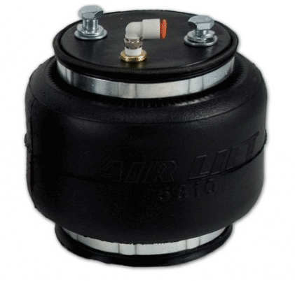
For example, an air spring. When inflating an air spring, or lift bag, to move a large mass, compressed air is fed into it. When the lift is complete, in order to deflate and remove the air spring, the air must be exhausted from it. The valve selected both to inflate and allow the bag to deflate is normally a 3-2 air valve.
Table of Contents
- What The Numbers 3/2 Mean
- 2 Positions
- Valve Ports
- Air Piloted Valves
- NC Valves = Normally closed valves
- NO Valves = Normally open valves
- Valve Actuators
- Detented 3-2 Air Valves
- Single Acting Devices
- The Big Difference – air can be vented
- How 3/2 Valves Work
- Speed Control
- Convert 3/2 to 2/2
- How To Draw A 3-2 Air Valve
- 3 Ports
- It Is Common To Draw A Valve In The Resting Position
What The Numbers 3/2 Mean
The first number in the 3-2 type air valve indicates the number of ports the valve will have. The second number indicates the number of positions that the air control mechanism inside this valve can have.
2 Positions
Most compressed air valves have two positions, but there are some that have three. I will cover three position valves on another page.
Valve Ports
Port 1 or port A on the 3/2 air valve will be the supply port to which the compressed air supply from the air compressor will be plumbed. This port is normally a female NPT or female metric threaded hole into which an appropriately sized air fitting will be threaded.
The fitting thread size must match the port thread in the valve. The other side of the fitting must also correspond to the air line size that will be connected to that fitting, that or select another fitting that fits both.
Port 2 or port B on a typical 3-2 air valve is the power or cylinder port. It’s typically a female port into which the appropriate fitting size and style is threaded. You will plumb from that port to the single acting actuator.
Port 3, possibly marked ‘E’ or even number ‘5’, is the exhaust port. On some 3-2 air valves this will be a female threaded port, and in others, simply an opening through which compressed air can escape from the valve when it’s shifted to the off position.
Be a bit careful as to the number of ports, as some 3/2 air valves only appear to have two ports with the third port, the exhaust port, actually exiting through the top of the solenoid. Normally this type of valve cannot have the exhaust restricted in any manner as doing so will negatively affect the operation of that type of air valve.
If port 3 is in the body of the valve, an exhaust flow control can be installed there and used to meter the outflow of air, and in so doing, adjust the speed of the actuator in one direction.
Air Piloted Valves
If the valve is air-piloted, meaning that it’s compressed air that operates this valve, then it will have an air port on one or both ends of the valve, as well as the three working ports. Usually these ports will be smaller than the working ports unless the working ports are 10-32 or 3 or 4 MM in size. Then the control air ports might be the same size. Look for these to be marked with two digit numbers, perhaps as 12 or 14.
NC Valves = Normally closed valves
Typically 3/2 compressed air valves will be NC, or normally closed.
This means that when the valve is not actuated it is in its resting state, and it is closed. Compressed air cannot pass through it. In this resting state there will be an open air path through the valve from the power or working port to the exhaust port.
NO Valves = Normally open valves
There will be some cases where having air pass through the valve to the application when it is not actuated is necessary for that air circuit. That being the case, a 3/2 NO (normally open) valve would be selected. Normally open means that when the valve is at rest compressed air passes through it from the supply to the cylinder port, and the exhaust port is blocked.
Valve Actuators
All 3/2 valves have actuators that will operate or ‘shift’ the air valve when required. An external button, a toggle, a lever or perhaps a solenoid actuator would be visible actuators.
Inside the 3/2 valve there will likely be an internal actuator – a spring – which will shift the valve to the off position when the external valve actuator is not being used. If the 3-2 air valve will shift itself back off when the actuator is not being used, then it’s known as a ‘spring return’ type valve.
Detented 3-2 Air Valves
When the 3/2 valve is operated, if it stays in its last selected position until an operator changes it again, then it is called a detented air valve.
Detented means it will stay where it’s put! Detented valves are useful when an operator needs to actuate a valve and then perform another operation while the detented valve continues to feed compressed air to the application.
Single Acting Devices
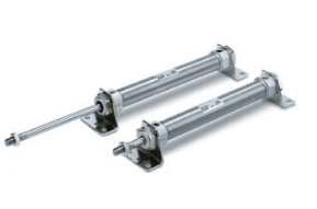
The 3/2 air valve is commonly used to supply compressed air to single acting cylinders or other similar compressed air using devices.
These could be air cylinders, air springs, or air diaphragms, anything that is configured to “automatically” let the air back out when the compressed air supply flowing to it is stopped.
For example, a single acting air cylinder may contain a spring that will drive the piston in one direction when the compressed air is shut off, saving energy since compressed air is being used only half the time or the air spring, referred to earlier on this page.
Picture a big rubber tire with a plate covering both sides of the center hole. Into one of the plates is a female port to allow an air supply to be connected. Place this air spring under something, and you have relatively low cost actuator able to supply tremendous loads as compressed air flows into it. When the lifting process is completed, the air flows back out through the exhaust port of the 3/2 valve, and the “tire” deflates. Neat!
The Big Difference – air can be vented
And that is the big difference between a 2/2 and the 3/2 air valve. With the 3/2 style, the air can get back out through the valve when necessary. With the 2/2 valve it cannot.
How 3/2 Valves Work
When the external actuator of the valve is released, an internal valve spring shifts the valve to off. The air supply coming into the valve becomes blocked so no more compressed air can flow through the valve to the application.
In shifting to off, the internal pathways of the valve open the working or power port that is connected to the actuator, and opens the exhaust flow path in the valve, allowing the compressed air in the actuator to flow freely back through the valve to the exhaust port and out to atmosphere.
Speed Control
If the exhaust port on a 3/2 valve is threaded, then you can install an exhaust flow control so that the exiting air can be metered to reduce its speed, and thereby, reduce the speed of the air using device, at least in one direction.
Convert 3/2 to 2/2
If the exhaust port in the 3/2 is threaded then, in the event that you actually needed a 2/2 air valve for your application, by threading a plug into the exhaust port of the 3/2 valve, you have created a 2/2 valve.
Some manufacturers don’t even manufacture 2/2 valves any more, since the conversion from 3/2 to 2/2 is simple, and this reduces manufacturing costs in that they only have to manufacture the one body for both. This strategy helps reduce inventory for them and for the users too.
Last point on the 3/2 valve. Two of them can be used to operated a double acting air cylinder in the event that a 4/2 air valve isn’t in stock when you need it. You simply plumb the cylinder / power port from each valve to one of the two cylinder ports and voila, as each 3/2 is actuated, the cylinder will extend and retract.
How To Draw A 3-2 Air Valve
This page is about drawing a 3-2 Air Valve. This is the second page in my step-by-step series of instructions on how to draw compressed air valves. The first page is about drawing a 2/2 air valve and can be found here.
Here is how to draw the 3/2 compressed air valve.
Until you get familiar with the process, I can almost guarantee that you will do a lot of erasing and changing of the lines, so I recommend that you do your drawing in pencil, and have an eraser handy too.
Start by drawing a square on your paper, a couple of inches square. You will find it easier if you use graph paper to help keep the lines straight.
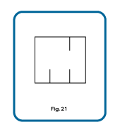
After you’ve drawn your box, add three lines inside the square as shown in Fig. 21.
The black outer square box depicts the valve body. The three little lines inside the square box represent the internal air passages and the air ports of the 3-2 air valve.
3 Ports
There are three compressed air ports in a 3/2 valve. The number of ports in an air valve body is indicated by the first number in the designation, and the second number indicates the number of positions that particular valve will have. This is a 3/2 valve, so it will have three air ports, and two valve positions.
You cannot tell from the outside how many positions a valve will have. The positions of the valve are selected by shifting the internal flow paths of a particular valve using some sort of a valve actuator.
Some circuit designers show the lines that are depicting the ports extending slightly through the wall of the valve when drawing their valve schematics. Some do not. I do not.
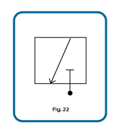
Fig. 22 shows the same box, but now we’ve connected up two of the ports, and modified the other one slightly, as shown in the graphic.
The black circle signifies the compressed air supply. It is flowing from the circle up to and into the 3/2 valve. This is a simple way to show that this valve is connected to an air supply, which is connected to the plant air mains, which are, in turn, connected to the compressor.
Compressed air cannot pass through the valve in Fig. 22 because the supply port inside the valve is closed. That is indicated by the small line teeing the top of the line coming from the air supply.
If this 3/2 valve was at rest, that is to say that there are no external valve actuators affecting the valve position, then it would be an NC (normally closed) air valve.
Note the line drawn from the top of the box to the bottom left, and that the line has an arrow head. This shows the open flow path of the air through this valve when it is in this position. The open flow path is from the top port, through the valve, and out the bottom port where the arrow head is located.
Please erase the small vertical lines that I asked you to draw in Fig. 21.
In Fig. 22 the port that is blocked or closed is the supply port. The port at the top of the box is the actuator or application port that is connected from that port by an air line to the end application ( a tool, actuator etc). The port that has the arrowhead pointing to it is now the exhaust port.
With the valve shifted into the position shown in Fig. 22, or if this is the at rest position for this valve, the supply is shut off and the actuator port is opened to exhaust which allows the compressed air to exhaust from whatever actuator is being used, to atmosphere.

Fig. 23 shows the same valve, but now in its shifted or alternate position. With the valve in this position, the supply air is moving through the valve to an application somewhere, and the other port, the exhaust port, is now blocked.
The air path inside this air valve will stay as shown in Fig.23 until this valve is shifted back, and then the flow path will revert to the one shown in Fig. 22 again.
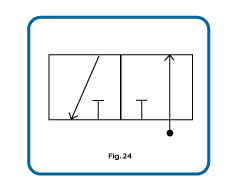
Fig. 24 takes the two drawings that we’ve made – Fig. 22 and Fig. 23 – and places them side by side in the same drawing, which is how the valve would be drawn on the air circuit schematic.
This depicts the flow paths of one 3/2 valve. The 3/2 valve has 2 positions, each position depicted by the drawing on one side or the other of the single valve schematic.
The way Fig. 24 depicts the valve, with the supply air coming into and through the valve, shows that when the valve is shifted to this position, then it is open, or passing.
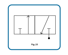
If the positions are reversed, as shown in Fig. 25 just below, then the valve is closed, or non-passing.
It Is Common To Draw A Valve In The Resting Position
It is customary to draw a valve in the position that it will be at rest, when the valve in not being acted upon by an exterior actuator, or when the air circuit that the valve is part of, has stopped functioning.
Without the actuators being shown in the drawings, a viewer cannot tell where this valve should be when it is at rest. In that case the air supply symbol, the circle, is drawn on the right side of the valve schematic.
Sometimes when the actual air circuit is stopped, one or some of the air valves making up that machine circuit, may be deliberately left in an actuated position. The supply line may be shown on the left in these circumstances. The overall circuit schematic will show the details if that is the case.
You will need valve actuators to complete this 3/2 valve schematic. Here’s how to draw valve actuators.
Additional valve reading:
- Types of Compressed Air Valves – Guide To Pneumatic Valves
- Pneumatic Flow Control Valves – What Are They, How Do They Work?
- Air Compressor Air Line Non-Return valves/Inline (In The Air Line) Air Check Valves Explained
- Check Valve Sizes
- What is Check Valve Cracking Pressure
- Air Compressor Troubleshooting Check Valve
- Air Compressor Unloader Valve Explained
- Unloader Valves On Twin V Piston Compressor Guide
- 5 3 Valves Explained
- 5-2 Air Valves
- 4-2 Compressed Air Valves
- Drawing a 5/3 compressed air valve
- Draw A 5/2 Air Valve
- Pneumatic Soft Start Valves
- Solenoid Pilot Air Valves
- Compressed Air Solenoid Valve Guide
- Air Compressor Auto Drain Valves Guide
- Needle Valve vs Ball Valve
- Globe Valve vs Ball Valve
- Globe Valve vs Gate Valve
- Butterfly Valve vs Gate Valve
Related Help Articles:
 Dangers of Compressed Air Explained – Is Compressed Air Really Dangerous? / Compressed Air Injury
 2/2 Air Valves Explained – Symbols, Schematics & How To Draw 2/2 Valves
 Winterizing RV With Air Compressor Guide to Blowing Out Waterlines to Winterize
 How To Draw A 5/2 Air Valve
 What is Check Valve Cracking Pressure – Guide