Want to draw a 2-2 air valve?
If you are involved with air circuit design or diagram a circuit for your own use, you may have to draw a 2/2 valve. There are standards of drawing pneumatic circuits and air valves that you should know and use.
Here are the steps to follow to draw a 2-2 Air Valve.

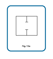
Start by drawing a square on your paper. It is easier to keep lines straight if you use graph paper. After you’ve drawn your box, add a couple of lines to the square, as shown in graphic Fig.15a above.
The outer square box depicts the valve body. The air paths through the valve and the two ports in a 2/2 valve are shown by a line or lines running into the valve body from the top and bottom center.
If the two ports are shown as in the drawing in Fig. 15a, then the air cannot flow through this 2/2 valve. It is drawn as closed. The cross bars drawn at the top of the lines inside the outer box show that air cannot flow through this valve.
Some circuit designers show the lines that are depicting the valve ports extending slightly through the wall of the valve. Some do not. I am of the latter persuasion.

If the lines are drawn as shown in the drawing in Fig. 16, then it shows that air can flow through this valve and this graphic depicts the valve as open.
Remember the definition of a 2/2 air valve? A 2-2 air valve is one that has 2 ports, and two positions,
In Fig.15a and in Fig.16 we show the same 2/2 valve in both possible configurations.
In one we show that the flow path through the valve is closed, and in the other we show the flow path as open. Both schematics are showing the same valve, in each of its two possible flow-path configurations.

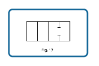
In Fig. 17 we have taken the two drawings, Fig.15a and Fig.16, and joined them together. Now we have the schematic for one complete 2/2 valve. On the left side of the drawing the valve is shown as open, and on the right side of the same drawing that same valve is shown as closed.
The positioning of the two graphics of the same valve, either with the air passing through it on the right side of the drawing, or the air not able to pass through it placed on the right side, has meaning. I will discuss this later.
Please let me reiterate to make it clear! Fig. 17 shows one 2/2 valve, with both possible configurations or positions for that one valve, drawn in a single graphic.
And that is how you draw the basic 2-2 air valve!
Of course, a 2/2 valve will not work all by itself except to turn air on and off? An air valve will typically need some sort of actuator to use the air. I mention this only to point out that a circuit drawing cannot just show the air lines and the various valve bodies and components, it must also show how each valve is to operate in the air circuit. Then, others looking at the same circuit drawing, will know what valve and what valve actuators to select for that circuit.
In this page, in order to keep the concepts and the drawing of the valves as un-complex as possible, I have not shown the valve actuators.
If interested, here is where to learn how to draw valve actuators.
Got a question about drawing 2-2 air valves?
Ask away in the comment form below
Want to draw a 2-2 air valve?
If you are involved with air circuit design or diagram a circuit for your own use, you may have to draw a 2/2 valve. There are standards of drawing pneumatic circuits and air valves that you should know and use. Here are the steps to follow to draw a 2-2 Air Valve.
Start by drawing a square on your paper. It is easier to keep lines straight if you use graph paper. After you’ve drawn your box, add a couple of lines to the square, as shown in graphic Fig.15a above. The outer square box depicts the valve body.
The air paths through the valve and the two ports in a 2/2 valve are shown by a line or lines running into the valve body from the top and bottom center.
If the two ports are shown as in the drawing in Fig. 15a, then the air cannot flow through this 2/2 valve. It is drawn as closed. The cross bars drawn at the top of the lines inside the outer box show that air cannot flow through this valve. Some circuit designers show the lines that are depicting the valve ports extending slightly through the wall of the valve. Some do not.
I am of the latter persuasion. If the lines are drawn as shown in the drawing in Fig. 16, then it shows that air can flow through this valve and this graphic depicts the valve as open. Remember the definition of a 2/2 air valve? A 2-2 air valve is one that has 2 ports, and two positions, In Fig.15a and in Fig.16 we show the same 2/2 valve in both possible configurations.
In one we show that the flow path through the valve is closed, and in the other we show the flow path as open. Both schematics are showing the same valve, in each of its two possible flow-path configurations. In Fig. 17 we have taken the two drawings, Fig.15a and Fig.16, and joined them together. Now we have the schematic for one complete 2/2 valve.
On the left side of the drawing the valve is shown as open, and on the right side of the same drawing that same valve is shown as closed. The positioning of the two graphics of the same valve, either with the air passing through it on the right side of the drawing, or the air not able to pass through it placed on the right side, has meaning. I will discuss this later.
Please let me reiterate to make it clear! Fig. 17 shows one 2/2 valve, with both possible configurations or positions for that one valve, drawn in a single graphic. And that is how you draw the basic 2-2 air valve! Of course, a 2/2 valve will not work all by itself except to turn air on and off? An air valve will typically need some sort of actuator to use the air.
I mention this only to point out that a circuit drawing cannot just show the air lines and the various valve bodies and components, it must also show how each valve is to operate in the air circuit. Then, others looking at the same circuit drawing, will know what valve and what valve actuators to select for that circuit. In this page, in order to keep the concepts and the drawing of the valves as un-complex as possible, I have not shown the valve actuators. If interested, here is where to learn how to draw valve actuators.
Got a question about drawing 2-2 air valves? Ask below!
