Air compressors consist of many components to ensure that your system provides high-quality compressed air, and so, it can often be difficult to understand the role of each component. This article will provide you with a few annotated diagrams of air compressor systems, with descriptions about each part to follow.
Table of Contents
- Single-Stage Air Compressor Diagram & Parts
- Two-Stage Air Compressor Diagram & Parts
- Rotary Screw Air Compressor & Dryer Diagram & Parts
- FAQs (Frequently Asked Questions)
Single-Stage Air Compressor Diagram & Parts
Let’s first take a look at this single-stage reciprocating air compressor!

Wheels, Handle & Fixed Foot
The wheels, handle & fixed foot on this single-stage compressor are there for the compressor’s portability. The handle allows you to lift the air compressor and then pull it, moving it to a different location with the help of the wheels. When you decide where you want to place the compressor, you lower it to the ground so that the fixed foot is rested on the floor, helping it remain in place.
If you’re interested in portable air compressors, please visit our 10 Best Portable Air Compressors guide!
Tank Receiver
A compressed air receiver tank, or otherwise referred to as an air tank or a compressed air storage tank, is everything it says it is… a tank that receives compressed air and stores it after it exits the air compressor chamber. This, therefore, provides you with an extra load of compressed air that you can draw upon without having to run your air compressor.
This is helpful when the duty cycle is a concern, and you do not want to exceed the compressor’s duty cycle by running the air compressor for more than it should be run. An air receiver tank is a type of pressure vessel by which it holds compressed air under a certain amount of pressure, for future uses.
For more information on air compressor tanks, visit our Compressed Air Tanks Explained – Sizing, Ratings, Portable Vs Stationary guide! Sometimes, you may wish to connect two air tanks together.
If you’re interested in Cleaning the Inside of Air Compressor Tank, visit our guide!
AC Cord
The AC cord of the air compressor is how you supply electricity (power) to your motor by plugging the cord into a suitable wall socket. Most compressors are designed to run on either 120 volts or 240 volts.
Some people opt for an extension cord so that they can place the air compressor in their preferred location (away from a power supply). Although this is not recommended as it may cause you to underpower the compressor, if you require to do so, please visit our What Size Extension Cord For An Air Compressor – Best Air Compressor Extension Cords guide!
Wondering how many watts does a compressor use? Visit our guide here!
Output Ports
The output ports, sometimes referred to as the discharge couplers, on this compressor are where you can connect your air hose or begin your piping system to lead towards and provide compressed air to your pneumatic tools.
Control Panel
The control panel will typically consist of the air compressor on/off switch, along with a pressure gauge, and pressure switch adjustment. It is absolutely mandatory to monitor pressures within a compressed air system. These indicators can be critical for gauging the performance of your compressor and your applications.
To accomplish this, pressure gauges are used. These units are available in a wide variety of sizes, ratings, materials, and configurations. One will be on the control panel so that you can observe the pressure within the tank. You may also come across a pressure adjustment control so that you can alter the tank’s pressure, along with the cut-in and cut-out pressures of the tank.
For more information on pressure gauges, visit our guide here!
Equipment Deck
The equipment deck on this air compressor is attached to the air receiver tank and is there to safely store the motor and pump.
Electric Motor
All air compressors have an engine and motor component. The motor’s role in the compression process is to drive the crankshaft which moves the piston in this single-stage compressor. This will then produce compressed air through an intricate mechanical process in the pump.
The motor typically contains a capacitor or even two, that modulate the current and voltage to the air compressor’s motor windings. If the capacitor was to fail, then so would the motor and the air compressor itself would not start or run properly. Here you will also likely find the thermal reset button, which trips if the motor overheats!
For more information, please visit our Air Compressor Motor Guide – HP, Types & Where to Buy Compressor Motors!
Belt Guard
The belt guard is there to protect the belt, pulley, and flywheel components of the motor. Without the guard, these vital components may be exposed to contaminants or damage which will stop the motor from working effectively if at all, and therefore, the compressor will no longer be able to produce compressed air. For more information on these components, visit our following guides:
- Air Compressor Belts Guide – Tightness, 2 Belts, Replacement & Where To Buy Air Compressor
- Motor Pulley sizing Guide – With Worked Example
In-Tank Check Valve
In-tank check valves have the purpose of preventing backflow through the compressor pump and are located directly screwed into the tank – essentially sealing the compressed air within the tank (which would otherwise leak out the unloader valve – more to follow on this component).
As the compressor is running and the air is being compressed, it will flow down from the pump head into the tank through the tank check valve. Since the check valve is a one-way valve, once compressed air gets into the compressor tank receiver, the only way it should get back out is via the discharge coupler/output port into which you connect your air hose.
For more information on in-tank check valves, visit our Air Compressor Check Valve: How It Works, What It Does, and Why It Exists guide!
Unloader Line
The unloader line is typically a small pipe that leads to the unloader valve. Unloader valves are an essential part of an air compressor and the whole pressure maintenance process. They are a critical function in ensuring that the air compressor is able to restart and operate sufficiently.
On a reciprocating compressor, like the single-stage compressor above, compressed air can be trapped over the piston when the compressor reaches the cut-out pressure and stops. If that air is unable to escape, a significant additional load is created for the start-up of the compressor motor when the pressure switch turns the compressor back on. That pressure build-up may be enough to prevent the compressor motor from starting due to overload.
When the compressor shuts off the typical unloader valve opens and unloads the air that may be trapped over the piston into the atmosphere, and that motor overload problem is resolved.
For more information on this, visit our Air Compressor Unloader Valve Explained, Adjustment & Common Problems guide!
Pump to Tank Interconnect
The pump to tank interconnect is the pipe in which the compressed air is passed from the pump to the tank for storage, through the in-tank check valve.
Pump
Air compressor pumps are vital components of the system. Their duty is to suck in atmospheric air and compress it into smaller volumes creating greater pressures. The air is then stored in a storage tank and released through the discharge port through a hose so that the kinetic energy of the pressurized air can be used to power your pneumatic tools and devices.
While all parts of a compressor work together, the pump is arguably the most important component. For more detailed information on air compressor pumps, please visit our Air Compressor Pumps Guide here!
Air Cleaner
The air compressor air cleaner, or in other words the intake filter, is a filter at the intake on the pump designed to block contaminants like dust and other debris in atmospheric air from entering the compression chamber in the pump.
If these contaminants were allowed to enter, they could potentially damage the internal mechanisms of the pump, causing premature wear and eventually complete failure. For more information, visit our Air Compressor Intake Filter – Replacing, Locating, Cleaning & Purpose Guide!
Drain Port/Valve
The drain port and drain valve at the bottom of the tank is there for the purpose of draining water from the tank to protect the air compressor system. Atmospheric air contains a certain level of water, and when this air is compressed, a natural byproduct is moisture, due to the increase in temperature of the air.
Naturally, the compressed air will cool when the air is stored within the tank, which leads to the moisture condensating and collecting at the bottom of the tank in the form of water droplets. These droplets can corrode the inside of the tank, causing the inner walls to rust. These rust particles, along with the water are not desirable to have in your airstream, especially not reaching your air tools.
Therefore, it is recommended to drain your tank after every use to remove the water from the tank and protect your compressed air system and attached air tools. For more information, please read our How To Drain Water From Any Air Compressor Tank – Remove Water From Air Tank & How Often To Drain Air Compressor Tank guides!
Two-Stage Air Compressor Diagram & Parts
Next up we have a two-stage stationary air compressor. Most of the parts of this compressor are similar to that of the single-stage, so I will only describe ones that haven’t been described yet!

Bolt-Down Feet
As this is a stationary air compressor, they typically have feet at the bottom of their vertical tank to allow you to bolt the feet into the ground to keep the compressor secure.
Safety Valve
A safety valve, otherwise known as a safety relief valve, is a critical safety device that must be used on all compression systems. These valves prevent catastrophic failure of the essential pressure equipment and piping.
All receivers must be equipped with a safety relief valve that is rated to open at a pressure no higher than the maximum rating on the receiver’s nameplate.
The OD of the poppet in the valve tends to be considerably larger than the orifice size so that the design allows the valve to open at high pressure and remain open until the pressure has dropped to a considerably lower pressure, usually about half of the valve’s pop-off pressure.
These are often confused with pressure relief valves, but they serve different purposes. A pressure relief valve is intended to vent excess pressure from the system. These valves are, in a sense, a type of pressure regulator. When the pressure exceeds a preset level, the relief valve opens and bleeds down the system.
Pressure Switch
Pressure switches are devices that open or close an electrical switch at a predetermined setting. These switches can be delivered with either fixed pressure settings or adjustable settings.
As it reacts to the pressure change in a compressed air system, the pressure switches either allow or drop an outgoing signal that is used to initiate an action. In the case of our air compressor, the action is to turn on or turn off the electric motor of the air compressor.
For more information on pressure switches, visit our Air Compressor Pressure Switch Troubleshooting & Buying Guide!
Welded Tank Tag/Machine Tag
The tags on the air compressor tank and the machine will provide all the relevant information about the system. The tank tag may include things like the shell and head thickness, along with the storage capacity in gallons.
The machine tag will specify all the important details of the compressor, including its horsepower, SCFM rating, maximum allowable pressure, voltages required, type of compressor, etc.
Intercooler
An intercooler is a mechanical heat exchanger used to cool compressed air back to near ambient temperature to increase its volumetric efficiency.
In order to deal with the increasing compressed air temperature, an intercooler will often be installed in the line between the two cylinders in a two-stage air compressor to help cool the air before it is sucked into the next cylinder for further compression.
For more information on intercoolers, please visit Air Compressor Intercooler Guide to Compressed Air Intercoolers
Compressor Stages (First and Second)
A two-stage air compressor works just like a single-stage compressor in that air is sucked into the cylinder and then trapped and compressed with the piston. But instead of then pushing the air into the storage tank, the air is pushed to a second smaller piston for a second stroke around 175 PSI before being sent to the storage tank for use with your attached pneumatic tools.
For more information on the different stages of compression visit our Single-Stage Compressors vs Two-Stage Compressors – What’s the Difference Between a Single-Stage and Multi-Stage Compressor guide!
Motor Controller
The motor controller is essentially the motor starter and will contain all the associated control circuitry. The motor controller will automatically shut down the unit when needed to conserve energy and will restart automatically when pressure decreases to a certain point.
A controller allows you to predetermine loading and unloading times. This will keep the unit running when needed to reduce the number of motor starts and prevent short standstill periods.
Isolation Valve
An air compressor isolation valve, otherwise known as a shut-off valve, is designed to shut off the airflow quickly if necessary. They typically consist of a lever that can be turned to immediately stop the flow of air from the tank heading down the lines. They will typically be either a gate valve or butterfly valve, and you can learn more about both in our Pneumatic Flow Control Valves – What Are They, How Do They Work?
Master Regulator
The master regulator is used to adjust the overall primary system pressure. You will set your tank regulator to a certain pressure and then utilize the master pressure regulator after the tank to control the pressure of the air through the lines and head to your pneumatic tools.
Most compressed air components are designed to operate at 90 psi. Therefore, supplying the distribution system with pressures higher than 90 psi is a waste. Using a master regulator on the output of the receiver will allow better utilization of the air charge, and consequently lower the cost per SCFM. This is especially true on two-stage air compressors like this example.
You should also be aware that a two-stage compressor can typically deliver 175 psi air, which is a high enough pressure to severely damage most air tools. Thus, showing the importance of a master regulator.
To learn How to Adjust an Air Compressor Pressure Regulator visit our guide here!
Refrigerated Air Dryer
Refrigerated compressed air dryers are one of the most commonly used types of air dryers due to their simple design, the fact they need very little maintenance, and their relative cheapness. The other types are desiccant and deliquescent air dryers.
In short, refrigerated compressed air dryers work by cooling down the air just like your refrigerator in your kitchen does to keep your produce fresh at the right temperature! For more detailed information on how they work, please visit our Refrigerated Air Dryer Guide – Best Refrigerated Air Dryers!
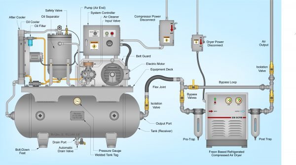
Rotary Screw Air Compressor & Dryer Diagram & Parts
Now, we switch our attention from reciprocating air compressors to a rotary screw air compressor.
Automatic Drain Valve
This component is just like the tank drain valve previously described, and is there for the same purposes. The key difference is that the valve is designed to automatically release water from the tank and saves you from having to remember to manually drain the tank. For more information, please read our Air Compressor Auto Drain Valves Guide!
Aftercooler
Aftercoolers are mechanical heat exchangers designed to remove the heat of compression and reduce the amount of water vapor in compressed air systems by condensing the vapor into a liquid form.
An air compressor aftercooler has these three crucial primary functions:
- Cools air discharged from the air compressor
- Reduces the moisture level of the compressed air
- Protects downstream equipment from excessive moisture and heat
For more detailed information, visit our Air Compressor Aftercooler Guide to Compressed Air Coolers! As you may have noticed, the two-stage reciprocating compressor example uses an intercooler, while this rotary screw compressor uses an aftercooler. If you’re interested in the key differences between the two, please read our Intercooler vs Aftercooler In Compressed Air System guide!
Oil Cooler
An oil cooler does exactly as its name implies, it cools down the oil within rotary screw air compressors that has become hot due to its role in lubricating the components involved in the compression stage.
Oil Filter
Within any compressed air system, there exists a requirement for filtration. Oil is a particular problem in oil-lubricated systems, as the oil mixes in with the air during the compression stage, and so, must be removed from the air supply before it is allowed to enter the receiver tank. Typically, a Coalescent Filter is the best form of filter to tackle oil contamination.
However, there are many types of filters available, all for different purposes. Visit our Compressed Air Filtration Guide – Types of Filters & Their Purpose for more information!
Oil Separator
An oil separator is a filter within an air compressor system that separates oil from the compressed air to protect systems components and your air tools at the end of the line. An air-oil separator is similar to the oil filter just described.
However, the oil-water separator works by separating the oils and lubricants from liquid water. The oil-water separator collects condensate from the air compressor tank, filters and dryer then remove the oil from the water prior to draining it.
For more information on both, have a read of our Air Compressor Oil Separator Guide – Air Oil Separators & Oil Water Separators!
Compressor Power Disconnect
When an air compressor, or any device that uses a motor, as a matter of fact, starts up it draws up to 7 times it’s running AMPs. This is referred to as the air compressor startup amps. While it may only last for an instant it is a huge draw and any components that are not built to suit that kind of draw will, over time, fail. A standard switch will likely burn up under this amperage, and so, a correctly sized compressor power disconnect is necessary.
Flex Joint
The flex joint is there simply to connect the air compressor’s tank to the rest of the system. Flex joints are used in places to help reduce any vibration stress and protect against thermal growth. Due to the fact that the next stage of the compressed air systems piping is likely to be mounted securely against the wall, flex joints compensate for slight misalignments between the compressor and the airlines for an easy and reliable connection.
Bypass Valves
Hot gas bypass, or HGBP for short, is essentially a valve that automatically regulates the cooling temperature in the refrigerant air dryer exchanger based on the pressure of the refrigerant.
Refrigerant driers typically have a lower system pressure when they’re partially loaded. The hot gas bypass valve opens when the pressure in the refrigerant circuit decreases to allow some of the refrigerant to circumvent the heat exchanger, which helps to eliminate the problem of over-cooling. Hot gas bypass valve adjustment allows you to keep your dryer running at its optimal temperature without risking the health of your system.
For more information on this, please visit our guide on the Benefits of Using Hot Gas Bypass on Refrigerant Dryers Explained!
FAQs (Frequently Asked Questions)
The basic parts of an air compressor include a motor, pump, storage tank, intake valve/filter, regulator, control panel, check valve, discharge line, outlet, and pressure switch to name a few!
You are likely to find the unloader valve mounted on or inside of the pressure switch on most air compressors. Therefore, when the pressure switch switches the air compressor off, the valve is actuated and unloads leftover air in the lines.
Air compressor breather elements allow air to be pumped within an air compressor system cleanly and efficiently. Breathers for air compressors keep the compressor and air tools that are being used to run smoothly and at their peak performance.
The two major components of an air compressor are its power source and compressing mechanism. The power source can be either an electric or fuel-powered motor while the compressing mechanism can be like a piston or rotary compression chamber for example.
If you have any questions regarding parts of an air compressor, please leave a comment below, with a photo if applicable, so that someone can help you!