Hey! This site is reader-supported and we earn commissions if you purchase products from retailers after clicking on a link from our site.
Pneumatic actuators are devices that convert the energy of compressed air or gas into a mechanical motion that regulates one or more final control elements. They are most commonly known for being highly reliable, efficient, and safe sources of motion control. Pneumatic cylinder actuators are amongst some of the most popular engineering devices.
This article will provide you with all the relevant information on pneumatic actuators, what they are, how they work, and pneumatic actuator control options.
Table of Contents
- What is a Pneumatic Actuator?
- How Do Pneumatic Actuators Work?
- Pneumatic Actuator Applications
- Types of Pneumatic Actuators
- Pneumatic Actuator Manufacturers
- When to Enhance Pneumatic Actuators Control
- Pneumatic Actuator Monitoring Considerations
- FAQs (Frequently Asked Questions)
What is a Pneumatic Actuator?
A pneumatic actuator, by definition, is a device that converts energy, typically in the form of compressed air, into mechanical motion. Across industries, pneumatic actuators are commonly referred to by numerous names, including pneumatic cylinders, pneumatic cylinders actuators, pneumatic valve actuators, air cylinders, and air actuators, all of which are the same device.
Pneumatic actuators are used as a form of automation control to help reduce mandatory human manual interaction with a system’s internal mechanisms, which is particularly beneficial for situations where you need an emergency shutdown or automatic modulation.
They typically consist of a piston, cylinder, and valves or ports so that the pneumatic actuator is able to convert the energy into linear or rotary mechanical motion, depending on whether the application is using pneumatic rotary actuators or pneumatic linear actuators.
Pneumatic linear actuators are suitable for fitting to angle seat control valves that are built for high temperature and steam applications, whereas rotary pneumatic actuators are better suited for fitting to quarter-turn valves depending on the specification of the application.
One of the most important features of a pneumatic actuator is the controller. A controller can be added to a pneumatic actuator for the sole purpose of positioning the valve per the requirements of the machine’s operator. The controller functions by sending a signal to the positioner that indicates where the valve should be positioned.
Since these controllers are pre-programmed to maintain a certain valve position, they adjust quickly upon any change in the controlled variable relative to the valve’s setpoint.
Benefits of Pneumatic Actuators
The majority of the benefits of choosing pneumatic actuators over alternative options like electric actuators is that they are typically more reliable and safer to use. Pneumatic vs electric actuators is easy, pneumatic cylinder actuators do not require ignition or electricity, which makes these devices highly sought after where parking and combustion are not tolerated.
Pneumatic actuators store compressed air and use it again efficiently without the risk of fire. On top of this, they’re extremely durable and can reduce the costs required to maintain their performance. The less maintenance you need to conduct, the longer the product lifecycle and, therefore, the greater output you will receive. Of course, it’s always good to carry out preventative maintenance, to learn more visit our Air Compressor Maintenance – How to Guide – Preventative & Ongoing!
Pneumatic actuators are generally affordable, user-friendly, and tend to have a simplistic structure. However, they can be very noisy and their position is often hard to control. Therefore, it is important to weigh the pros and cons of a pneumatic actuator within the context of the desired application before making an investment.
How Do Pneumatic Actuators Work?
A pneumatic actuator is heavily reliant on the presence of pressurized gas or compressed air entering the chamber where pressure is built up. A controlled kinetic movement of a piston or gear in a straight or circular mechanical motion is then created when the built-up pressure exceeds the required level in contrast to atmospheric pressure outside of the chamber.
Pneumatic actuators transmit energy through their stem with the help of both air pressure and spring force, hence why they are often referred to as spring return pneumatic actuators. Within the housing of the actuator, two separate air chambers are created by a rubber diaphragm. The upper chamber receives air from an opening which is located at the top of the actuator housing.
A spring that applies force to the diaphragm is located in the bottom chamber so it halts mechanical stops in the upper chamber. Roughly halfway through the bottom chamber, a local position indicator can be found connected to the stem, which indicates the position of the valve.
The fluctuating air pressure located in the upper chamber is what controls the indicator. The positioning device is very complex. An input connection for the control valve, a supply air connection, a supply air input connection, a supply air vent connection, and a feedback linkage are the parts that are featured on the outside.
The inside of the chamber features an elaborate series of airlines, linkages, valves, necessary adjustments, and electrical transducers. The spring will continuously hold the valve open if there is a lack of air. More force is applied to the diaphragm as the air supply increases, which will overpower the force of the spring, and therefore, subsequently make the valve close.
The valve’s positioning typically depends on how much air is supplied to the machine’s top chamber. Once the desired position is achieved, the valve is held in position, and the air pressure stops changing.
A prototypical actuator uses this external compressive force (air or gas) to move a piston along the inside of a hollow cylinder and build up the pressure. This pressure then generates a linear force relative to the piston’s pressure differential multiplied by its surface area, which is then used to move a load along a straight line.
Pneumatic linear pressure actuators have been in service for decades but enhancements to their diaphragm design and sealing capabilities have vastly improved the technology’s efficiency and scope of functionality in recent years.
Rotary pneumatic actuators differ from linear designs in they have a torque generated as opposed to the linear motion of linear designs. This can be easily accomplished by transferring the linear motion of a piston to a rotating component or vice versa.
Pneumatic Actuator Applications
Pneumatic actuators are well suited to a wide variety of application types, serving many different areas within numerous industries. In addition to being fast, economical, and reliable, pneumatic actuators are also cleaner and safer than other solutions, which makes them ideal for manufacturing, packaging, palletizing, material handling, food and beverage, and many more applications.
Some of the most common applications of pneumatic actuators include:
- Air compressors
- Aviation
- Biotechnology
- Combustible automobile engines
- Food processing
- Lifting, pushing, rotating, and moving equipment
- Material Handling
- Packaging & production machinery
- Pharmaceutical
- Railway application
Types of Pneumatic Actuators
To be able to deliver to such a wide range of applications and industries, the variety of pneumatic actuators available is very versatile. They range from compact small pneumatic actuators that are designed that are used for small handling applications to large actuator designs that are used for the most powerful jobs. They even have rodless designs that provide stroke lengths like conventional cylinders, providing a much smaller footprint.
Each actuator type and its variations offer a unique set of characteristics and advantages based on the applications they serve. Let’s look at some of the most common and specialized types.
Types of pneumatic actuators list:
- Bellows (specialized)
- Flexible diaphragm cylinders (specialized)
- Grippers (specialized)
- Knife gate cylinders (specialized)
- Mini and round body cylinders (common)
- Profile and tie-rod cylinders (common)
- Rack-and-pinion rotary actuators (specialized)
- Rodless cylinders (common)
- Screw-in cylinders (specialized)
- Short stroke and compact cylinders (common)
- Vane style rotary actuator (common)
Let’s take a look at each in more detail!
Bellow Pneumatic Cylinder Actuators
Bellows are a type of rodless pneumatic actuator that is capable of providing high forces in a small installation space. They have an impressively low maintenance requirement when compared with conventional pneumatic cylinders as they do not have mechanically moving parts.
Convoluted bellow cylinders are the most popular variant and feature a corrugated natural rubber body that helps the product absorb vibration, shock, and noise, making it perfect for these isolation applications. They can also be used for applications that include tensioning, lifting, and pressing.
Flexible Diaphragm Pneumatic Cylinder Actuators
Flexible diaphragm cylinders are virtually frictionless and can be actuated at low pressures to provide precise balancing of forces, especially in finely tuned systems.
Gripper Pneumatic Cylinder Actuators
Gripper pneumatic cylinder actuators offer parallel or angular motion which allows them to be commonly used for work holding, pick-and-place, and robotic arm applications.
Knife Gate Pneumatic Cylinder Actuators
Knife gate pneumatic cylinder actuators are typically specifically designed to automate knife gate valves, which are commonly found in power, wastewater, mining and mineral processing, pulp and paper, and chemical industries.
Mini and Round Body Pneumatic Cylinder Actuators
Mini and round body cylinders are available in a wide range of sizes, strengths, and various properties, which make them excellent solutions for a wide variety of applications. These types of pneumatic actuators are known for their lightweight, highly customizable, affordable, and infinitely adjustable force control. This makes them ideal for applications like small handling and within the food industry.
They are primarily not repairable, but these cylinders will typically have aluminum or polymer end caps crimped to a stainless-steel tube. This makes them a very attractive, popular, and cost-effective solution for basic pushing and positioning applications.
Some models may even feature an all-stainless-steel construction to withstand any potential caustic or corrosive environments. The hygienic designs have a clean and smooth surface and are also available to prevent the accumulation of dirt or bacteria in applications that require strict cleanliness.
Profile and Tie-Rod Pneumatic Cylinder Actuators
Profile and tie-rod pneumatic cylinder actuators are very well-proven, universal solutions that are capable of providing precision and regulated force even in applications where high force and long stroke length are requirements.
These designs are known to be sturdy, reliable, and highly configurable, and are frequently used in general automation applications. They are also available in a number of designs in order to meet a wide range of applications, needs, and budgets.
Profile and tie-rod pneumatic cylinders are typically manufactured to NFPA and ISO dimensional standards to simplify installation and worldwide interchangeability and are available in aluminum, steel, and stainless-steel constructions.
Rack-and-Pinion Rotary Pneumatic Cylinder Actuators
Rack-and-pinion rotary pneumatic cylinder actuators generally consist of a piston and rack that moves linearly to cause a pinion gear and output shaft to rotate. In most cases, they are commonly used to open and close valves or dampers while providing high torque and adjustable rotation angles.
Picture a standard double-acting air cylinder. Now, remove the piston rod and add another piston inside the cylinder barrel. Between the two pistons attach a rack, and have that rack intersect with a pinion located at the center of the cylinder. As compressed air alternately flows into one airport and then the other in the end caps of the cylinder, the pistons and the rack move back and forth.
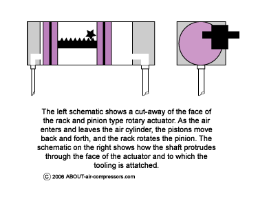
The teeth on the rack mesh with the teeth on the pinion gear, imparting a rotational movement to the pinion as the rack moves. The pinion gear is connected to a shaft that protrudes out the side of the cylinder and voila… you have a rack-and-pinion rotary actuator.
Depending on how long the cylinder barrel and the corresponding rack is, this type of rotary actuator can impart rotation to the shaft, arm, and tooling from 0 degrees up to whatever may be required for the application. The longer the cylinder barrel, the more the rotation of the shaft.
Rodless Pneumatic Cylinder Actuators
Rodless pneumatic cylinder actuators do not have a piston rod, like other types. This eliminates the risk of rod-bending or buckling when compared to conventional cylinders. The rodless designs offer high functionality and drive force in a small amount of space and are available in a wide range of sizes and designs, making them fundamental for automated handling technology.
Many rodless cylinders incorporate some form of load guidance feature such as slide bearings inside the cylinder or external rails with runner blocks to help bear heavy loads with high repetitive precision. Some designs may even feature an oval-shaped piston that is capable of providing the necessary great resistance to side loads and a low overall height design.
Common applications for these types of pneumatic cylinders range from simple material flow to door openers and from cutting and drive processes to material handling applications that involve light to heavy loads.
Screw-In Pneumatic Cylinder Actuators
Screw-in pneumatic cylinder actuators are primarily used for tensioning and positioning of small components and, because of their threaded design, and so, they can be installed directly into working environments without taking up much space.
Short Stroke and Compact Pneumatic Cylinder Actuators
Short stroke and compact pneumatic cylinder actuators are shorter than the typical standard pneumatic cylinder by up to between 50% or 60% but provide the same concentrated power, precision, and reliability that is necessary.
Their compact size allows them to fit perfectly in practically any limited installation space machine environment, making them great for applications like manufacturing, packaging, palletizing, semiconductor, and robotics. Short stroke and compact pneumatic cylinder actuators are easy to mount and available in single- and double-acting pneumatic actuator models as well as non-rotating versions.
Vane Style Rotary Actuator
The vane style uses similar technology and concepts to an air tool or air motor. Compressed air flows into one of two airports in the actuator’s vane housing via an airline from the control valve. As the compressed air moves into the vane actuator, it tries to flow from high pressure towards the atmosphere – and in so doing it rotates the vanes inside the housing and imparts rotary motion to the shaft.
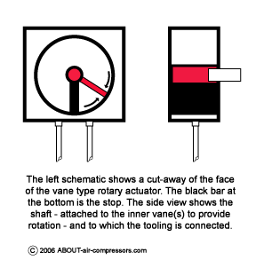
Vane-type rotary actuators are usually double-acting. Compressed air flows alternately to one of two airports in the housing, providing rotary motion in one direction when the control valve is shifted one way, and the rotary motion in the other direction when the valve is shifted back and air flows into the other port.
It is important to calculate the moment of inertia for the load the rotary actuator is intended to move, in order to select an actuator with sufficient force. This involves calculating the distribution of the mass of the load as it moves at a continually varying distance from the axis of the actuator shaft.
For example, a 1 Kg load placed axially to the shaft will require a certain amount of force to rotate it. That same load, placed tangentially from the center of the shaft, will require a much greater force to move and to stop it.
When it comes to determining how big a rotary actuator you need for the application, I recommend that you get your staff engineer involved, or use the charts and guidance that is available from the actual manufacturer of the rotary actuator. Much support material for sizing actuators can now be found online, from the manufacturer’s website.
It is easy to make a mistake in calculations which will result – at best – in a rotary actuator that will not rotate, and at worst, damage to people or equipment. So please be careful!
Pneumatic Actuator Manufacturers
I have picked out some of the leading manufacturers of pneumatic actuators:
- ABB
- Bürkert
- ElectroCraft
- Emerson
- Ultra Motion
ABB
ABB is a world leader in the design and supply of test, measurement, and actuation instruments for demanding industrial applications. We provide a proven range of pneumatic actuators suitable for damper applications with additional functionalities suiting them to a broad range of final control elements.
ABB Contact Details
ABB
305 Gregson Dr,
Cary,
NC 27511
T: +1 (203) 856-2360
E: [email protected]
Bürkert
Bürkert is one of the world’s leading manufacturers of measurement and control systems for liquids and gases.
Bürkert Contact Details
Bürkert USA Corp.
11425 Mt Holly-Huntersville Rd,
Huntersville,
NC 28078
T: +1 (800) 325-1405
E: [email protected]
Electrocraft
ElectroCraft hybrid stepper-based linear actuator solutions provide original equipment manufacturers the precision, performance, and reliability that is required for a wide variety of motion control positioning applications.
From medical and laboratory equipment to industrial machinery, ElectroCraft offers configurable or completely customizable solutions in three unique product designs: linear actuator (non-captive), leadscrew motor (external linear), or guided linear actuator (captive).
Electrocraft Contact Details
ElectroCraft, Inc
2 Marin Way, Suite 3
Stratham,
NH 03885-2578
T: +1 (833) 392-0390
E: [email protected]
Emerson
Emerson has two focused business platforms, their Automation Solutions, and Commercial & Residential Solutions, which combine advanced technologies, industry-leading expertise, and an insatiable curiosity about the world to create sustainable solutions for their customers.
Emerson Contact Details
Emerson US and World Headquarters | Emerson Electric Co.
8000 West Florissant Avenue, P.O. Box 4100,
St. Louis, MO 63136,
United States
T: +1 (314) 553 2000
Ultra Motion
Ultra Motion designs and manufactures precision electromechanical actuators, and related products, for multiple industries including aerospace, medical, industrial automation, defense, research, and more. Our areas of expertise include extreme power density, fully integrated closed-loop servo actuators, multi-turn absolute position sensors, and challenging environments like space, deep sea, vacuum, etc.
Ultra Motion Contact Details
Ultramotion
22355 CR 48, #21
Cutchogue, NY 11935
T: +1 (888) 321-9178
E: [email protected]
When to Enhance Pneumatic Actuators Control
There are several conditions that can affect a pneumatic actuator’s performance, which leads to the need to enhance the control. How to control pneumatic cylinder position? Inconsistent air pressures or variable payloads can drastically change the operating speed of the actuator. It’s also likely that the wearing or overdue maintenance of internal or external parts and mechanisms can have an impact on the ability of the actuator to operate at its optimum.
If a human was operating the controls manually, it is easy to observe the equipment and make adjustments where necessary, but this isn’t the case. Most modern-day designs of machinery are automated and have more complex sequences and interactions, necessitating monitoring to ascertain the correct operation.
Whenever one action directly impacts a subsequent action, it is crucial to ensure that the position of the first step has been achieved before moving on to the second step. Position sensors are used to perform this function and they let the automation system proceed to the second step at the exact moment and only when the first is completed. This allows for sequential functionality can be maintained even if equipment performance and speed change over time.
Many users will often choose to monitor each and every pneumatic cylinder control valve action. Most pneumatic cylinders are capable of operating in either extended or retracted positions. If position switches are installed for each case, you can configure the control system to alarm if a cylinder has not reached the commanded pneumatic cylinder position control when expected.
It is also possible to add even more switches that are able to indicate when actuators reach the midway positions. Another possible control enhancement is for the system to evaluate the time it takes for an actuator to move to the commanded position. The nominal actuation time of each of the actuator’s motions can be determined during equipment setup and tuning.
Therefore, the pneumatic cylinder speed control system can be configured so that any actions that take longer than expected, even if they are eventually completed, will trigger a warning using this crucial information. This allows end-users to be notified of any impending troubles before there are able to lead to complete failure.
Pneumatic Actuator Monitoring Considerations
It’s not as simple as just enhancing the position control pneumatic cylinder and monitoring the pneumatic cylinder stroke control; there are multiple other considerations that must be understood. The position of the actuator can be sensed on the actuator itself or on the driven equipment, depending on the requirements. In all possible cases, the sensor environmental protection ratings (NEMA or IP) must be suitable for the installation location.
A proven method that can be consistently applied throughout a machine is by installing sensors on the actuator. The only problem here is that they will not sense any failures within the mechanical linkages or mechanisms, and so, designers will opt for installing position switches on the driven equipment.
Many pneumatic cylinder actuators include slots or other accommodations so that they are ready to accept compatible position switches. The most common styles are T-slot, round, and dovetail. Some sensors are configured to work with mounting bands or other adapter brackets for applications that don’t have those features.
A positive sensing arrangement also requires the internal piston to be magnetic. To indicate the presence of the piston, and therefore the mechanism, the position switches can be mounted in one or more locations on the cylinder surface.
Although older-style mechanical reed switches are readily available and somewhat less expensive, solid-state switches provide a more contemporary and reliable option because they have no moving parts which wear out. When it is more critical to positively identify the position of driven equipment, it may be better to use traditional limit switches that are external to the cylinder. These can be mechanical or solid-state proximity types and each may require additional metal targets or fittings to activate their switches.
Regardless of the position-switch location, it is crucial to have the proper electrical characteristics. It is very common to use normally-open (NO) switches that close when the position is sensed. However, there are cases where normally-closed (NC) would be the more desirable choice.
Most switches are configured only one way or the other. From an electrical standpoint, it is always smart to choose the logic to be failsafe. This means that if the wiring or switch were to fail, the equipment will come to a stop in the safest way possible.
Pneumatic Actuator Cost Considerations
Sensing elements are always worth the investment, especially when they’re required for critical applications. However, it’s possible that the cost of adding switches to both ends of a basic pneumatic cylinder may equal the cost of the cylinder itself. Adding sensing elements is going to create a ripple effect of material and labor impacts.
The switch parts must be selected to match the exact physical sensor needs and the electrical characteristics of the proposed control system. The sensors on mechanical and electrical wiring diagrams must be provided by the designers. During the installation, electricians must install the field wiring and ensure it is carefully routed to accommodate any potential motion.
Each actuator must be operated through its range during startup and the technicians must adjust the position switches accordingly. Actuator automation has the potential to significantly help operational and maintenance personnel down the road, especially when the system is configured with sufficient diagnostics to indicate the trouble as previously described.
The only concern of this is that sensing elements introduce additional maintenance concerns because they may fail or drift out of adjustment. The bottom line of the cost considerations is that pneumatic cylinder position control and monitoring elements are a valuable addition but introduce certain costs which must be considered and weighed against expected benefits.
Pneumatic Actuator Hybrid Approaches
To help contain costs, often designers will pursue a more hybrid approach to specifying actuator controls, especially when developing systems or subsystems that will be produced in sheer quantity. It’s very common for engineers to over-specify the instrumentation when a piece of equipment is first undergoing development, leading to sensors being put in all possible locations.
While the system is in prototype mode, this will allow them access to use the automation platform for tracking cycle times and other operational parameters, and then fine-tuning operation, adjusting the timing, and troubleshooting any potential problems.
Once the machine is running as intended, it is then possible for the designers to evaluate exactly which position switches are required for the specific operation and maintenance. During this very valuable phase, all the unnecessary elements can be removed to lower costs while still providing the instrumentation needed for the desirable safe and reliable operation.
Pneumatic actuators are important components for many various types of machines. Whether they are manually controlled or operated as part of an automated system, there are many reasons to monitor actuator position and integrate these considerations and information into the control scheme. Careful attention must be paid to the required physical and electrical characteristics that will help designers choose the best fit for absolutely any application.
FAQs (Frequently Asked Questions)
The most common types of pneumatic actuators include mini and round body cylinders, profile and tie-rod cylinders, rodless cylinders, along short stroke and compact cylinders. Each actuator type and its variations offer a unique set of characteristics and advantages based on the applications they serve. There are also a number of specialized pneumatic actuators available like grippers!
A pneumatic actuator is heavily reliant on the presence of pressurized gas or compressed air entering the chamber where pressure is built up. A basic method of controlling pneumatic actuators is the controlled kinetic movement of a piston or gear in a straight or circular mechanical motion which is created when the built-up pressure exceeds the required level in contrast to atmospheric pressure outside of the chamber. The valve’s positioning typically depends on how much air is supplied to the machine’s top chamber. Once the desired position is achieved, the valve is held in position and the air pressure stops changing.
If you are looking to control the speed of a pneumatic cylinder, the most effective way is to use a speed control valve or flow control valve to vary the amount of flow out of the exhaust port of the cylinder. In order to adjust the speed, the flow of air must be controlled, whereas adjusting the force of the cylinder should be handled by controlling the pressure. Although adjusting the pressure may have an effect on the speed, it is not a recommended method to control the speed.
The best way to control a double-acting pneumatic cylinder is by using a 5-port valve. These types of valves allow for the double-acting pneumatic cylinder to be pressurized and exhausted on both sides of the cylinder for extension and retraction.
Pneumatic actuators typically rely on the presence of some form of pressurized gas or compressed air entering a chamber where pressure is built up. Once this pressure exceeds the required pressure levels in contrast to the atmospheric pressure outside of the chamber, it creates a controlled kinetic movement of a piston or gear which can be directed in either a straight or circular mechanical motion, depending on the design of the pneumatic actuator.
If you have any questions regarding pneumatic actuators, please leave a comment below, with a photo if applicable, so that someone can help you!
