This article will provide you with all the relevant information, along with YouTube demonstrations, on how to create your own air cylinder-driven pneumatic can crusher following some simple steps!
Table of Contents
- Equipment Needed to Make an Air Cylinder Driven Pneumatic Can Crusher
- How to Make an Air Cylinder Driven Pneumatic Can Crusher
- Existing Pneumatic Can Crushers Readily Available
- FAQs (Frequently Asked Questions)
- Reader Questions and Responses
Equipment Needed to Make an Air Cylinder Driven Pneumatic Can Crusher
To be able to make your own air cylinder driven pneumatic can crusher, all you will need is the following (in addition to your air compressor of course):
- Double-acting pneumatic cylinder
- Mushroom button pneumatic mechanical valve
- Pneumatic hose
- Quick fittings
I’ll now provide some examples of these parts that are readily available on Amazon!
Double-Acting Pneumatic Cylinder
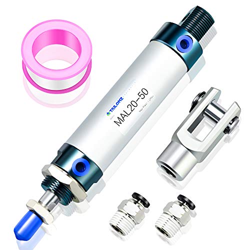
- 【Port size】 PT1/8【Bore】 3/4 (20mm)【Stroke】2(50mm).
Prices pulled from the Amazon Product Advertising API on:
Product prices and availability are accurate as of the date/time indicated and are subject to change. Any price and availability information displayed on [relevant Amazon Site(s), as applicable] at the time of purchase will apply to the purchase of this product.
Mushroom Button Pneumatic Mechanical Valve

- Product Name : Mechanical Valve;Model : MSV-86522PB;Type : Direct Action
Prices pulled from the Amazon Product Advertising API on:
Product prices and availability are accurate as of the date/time indicated and are subject to change. Any price and availability information displayed on [relevant Amazon Site(s), as applicable] at the time of purchase will apply to the purchase of this product.
Pneumatic Hose

- Product Name : Polyurethane Air Hose;Material : Polyurethane(PU); Color : Blue;Weight :204g; Package Content : 1 x Polyurethane Air Tube
Prices pulled from the Amazon Product Advertising API on:
Product prices and availability are accurate as of the date/time indicated and are subject to change. Any price and availability information displayed on [relevant Amazon Site(s), as applicable] at the time of purchase will apply to the purchase of this product.
Quick Fittings

- Material: plastic, copper nickel plating
Prices pulled from the Amazon Product Advertising API on:
Product prices and availability are accurate as of the date/time indicated and are subject to change. Any price and availability information displayed on [relevant Amazon Site(s), as applicable] at the time of purchase will apply to the purchase of this product.
In regard to choosing the right air compressor for this task, you will only need around 60 PSI to be able to successfully crush a can. Therefore, any air compressor, regardless of its size or tank volume, will be capable of being used for this project as they all can comfortably provide 60 PSI.
I would recommend keeping the air compressor at around 100 PSI and then using a regulator between the compressor and the can crusher to regulate the air pressure down to 60 PSI. This way you can also ensure that you do not fall below 60 PSI through the cylinder from pressure drops.
How to Make an Air Cylinder Driven Pneumatic Can Crusher
The first stage of making an air cylinder is as simple as connecting all the parts listed above. Here’s a step-by-step guide on how to do so:
How to Make an Air Cylinder Driven Pneumatic Can Crusher
- Cut Pneumatic Hose
The first step is to cut the pneumatic hose to a suitable length. The two lengths will vary slightly, but measure how far you want the pneumatic mechanical valve button from the double-acting cylinder and cut the hose appropriately.
- Insert Quick Fittings
Now you can insert quick fittings onto the pneumatic mechanical valve button so that you’re then able to connect the air hose from the button to the cylinder.
- Connect Air Supply
After securely connecting the air hose from one side of the pneumatic mechanical valve button to the two ports on the double-acting cylinder. Now, you can connect the other side of the pneumatic button to the air hose coming from your air compressor using quick fittings.
This is a very simplified method, that can be further observed in the YouTube demonstration below!
The proceeding steps will involve creating a box for the can crusher to sit inside of. This can be made out of a variety of materials, with the most popular being metal or scrap metal. But, I’ve also read a few comments across my research saying that people opted for wood. Here’s another YouTube demonstration that may be able to give you some inspiration for the type of box you need to create.
Existing Pneumatic Can Crushers Readily Available
I have picked out the following 2 examples of pneumatic can crushers that are readily available for purchase on Amazon, these may give you additional inspiration on how to design your box/can crushing element.
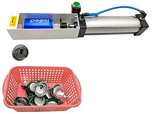
- Air Cylinder Can Crusher, Just press the button of the valve to smash almost all kinds of aluminum cans.
Prices pulled from the Amazon Product Advertising API on:
Product prices and availability are accurate as of the date/time indicated and are subject to change. Any price and availability information displayed on [relevant Amazon Site(s), as applicable] at the time of purchase will apply to the purchase of this product.

- Size: Bore: 2.48 inch, Stroke:7.9inch
Prices pulled from the Amazon Product Advertising API on:
Product prices and availability are accurate as of the date/time indicated and are subject to change. Any price and availability information displayed on [relevant Amazon Site(s), as applicable] at the time of purchase will apply to the purchase of this product.
FAQs (Frequently Asked Questions)
To make a homemade pneumatic can crusher, all you need is an air supply (air compressor), double-acting pneumatic cylinder, button pneumatic mechanical valve, quick fittings, and pneumatic hose. By connecting the button to the double-acting cylinder with the quick fittings and pneumatic hose, you can need to connect the button to the air supply so that every time you press the button, compressed air will flow through the button and to the cylinder causing it to extend, and crush a can.
A double-acting cylinder with a 2.5″ cylinder bore and a 5-8″ cylinder stroke should be a sufficient size and force to be able to crush cans.
Pneumatic can crushers are devices fitted with a pneumatic cylinder (pressurized tank) that pumps air with a tremendous force to set the crushing device into motion, which then falls onto the can. All you have to do is just place the can in a chamber that is fitted with the crushing device, and the force of the cylinder will crush the can.
Reader Questions and Responses
Question
This is how I made an air cylinder driven pneumatic can crusher, for two or three sizes of cans, actually:
This is used mostly for 12 oz cans but can handle 24 oz cans.
Small cans crush nicely at about 85 psi, while large cans need closer to 110 to fully crush.
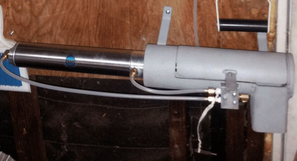
So… I made up the thing shown in the first pic so I can turn on either regulated 85 or unregulated 100-125 air. (there are two filters in the line to the blue hose, and I plan to add another one right before the FR in the picture).
The second picture shows a 12 oz can just prior to crushing.
1. Does it matter to the cylinder whether it is pressurized when not in use?
2. Would putting between the cylinder and the ram to keep it from fully retracting while crushing small cans hurt anything?
3. Other comments? The blue hose will eventually drop straight down, but I have not seen any moisture issues.

Response
Doug, good on you. One of these has been on my to-do list for a long time, and I have never gotten around to it.
Question 1) No, the air cylinder will suffer no ill effects if left pressurized. If, however, you have a cylinder piston seal leak, then air will blow by, and your air compressor will cycle for nothing if the leak is not repaired.
2) If this … “would putting between the cylinder and the ram ” means you want to put a stop of some sort, no, the cylinder doesn’t care where the rod stops. If the stop is stronger than the force generated by the cylinder, the piston inside the cylinder just halts travel.
Suggestion… though the can cover is closed when the action cycles, what if it isn’t? You have created a potential pinch point. Get around that by adding an anti-tie-down circuit that requires two buttons, arms-length separated, to be pushed and held to cycle the air cylinder. That way both hands have to be away from the crusher when it is moving.
Also, why not run it at the higher pressure all the time? A single cycle of the crusher will use very little extra air, and it will always be at the pressure needed to handle the big cans. If the crusher air cylinder moves too fast, simply add a flow control that slows the cylinder, but does not take away any of the force.
Thanks for this. Good one!
Question
I got the primary air filter added to the main air.
The valves are both “off”, and there is very little air reserve between the (red handle) valves and the crusher switch/cylinder.
If I were doing an air brake check on a vehicle, 3psi loss in one minute would be acceptable. This system bleeds about 1psi per minute.
I don’t yet know if it’s the cylinder or the switch or both doing the leaking. Gotta get some caps/plugs to do that.
The question: is there a rule of thumb or whatever for acceptable leakage?
Response
As far as I know, it’s user-determined, Doug. A major plant might blow off 10% of their air production to dozens of leaks and find that acceptable and a single fixture that leaks at all may throw off a clamp mechanism leading to product failures, and in that case, no leak at all is their norm.
If you don’t want to waste air through a small leak, and couldn’t be bothered finding it, install a ball valve before the system shuts off the air there.
You don’t need caps to check your cylinder. Pressurize the system, then fold the line that is pressurized to the cylinder. Feel at the exhaust port of the valve. If air is leaking out of the exhaust port of the valve and it stops when you clamp the pressurized airline going to the cylinder, then the leak is in the cylinder. If the air continues to leak out of the exhaust of the valve with the pressure line to the cylinder clamp, then you have a seal leak in the valve.
Soap and water will find any fitting leaks.
Question
A remark, actually…
In addition to what you already have on the gauge page, there is at least one more failure mode: leak(s).
I had an air tank that had been working ok for some time…
Then, overnight, it went from 120psi to 60psi.
Went looking for leaks, couldn’t find any.
Finally realized that while it went from 120 to 60 overnight, it then didn’t leak down further.
Knowing how most gauges work, I concluded the gauge must be cracked internally.
And it was: new gauge, and leak gone.
If you have any questions regarding making an air cylinder driven pneumatic can crusher, please leave a comment below, with a photo if applicable, so that someone can help you!