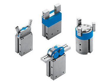
There are a host of companies manufacturing compressed air driven grippers now. Here is information about selecting and using grippers in your manufacturing processes.
Custom built grippers can work well yet their use can have drawbacks. Custom built compressed air grippers are usually large and weigh a lot. For large pick and place applications, a large gripper is fine. For smaller, high speed pick and place, you need a gripper built for that use, low in weight and high in speed.
Table of Contents
Heavy Tooling = Grippers Having Less Payload
Of course, the heavier the end tooling is, the less load capability of the pick and place apparatus, and the slower the cycle of the system. If high speed is what you need you will do better buying a gripper that is ready to use and the right size and weight for the application since compressed air equipment manufacturers have risen to the occasion, churning out standard air grippers to suit many applications, grippers that are compact in size, light in weight, lightning fast, and able to handle extraordinary loads for their compact size.

How Grippers Work
Almost all air grippers contain a double acting air cylinder to impart motion to the gripper gearing and gripper fingers.
The gripper gearing produces movement in the gripper fingers when the piston on the internal cylinder cycles. Air in one port and the fingers open; air in the other, fingers close.
Gripper fingers are designed for tooling attachment. Tooling might be a simple as rubber nubs or some such, to enable the gripper fingers to better clamp and hold a part, or secondary tooling, quite possibly also compressed air operated, to accomplish another task once the gripper fingers have grasped the item.
Tips On Gripper Use
The first thing to be concerned about is if the gripper has the load carrying capacity for what is to be gripped and lifted. If the gripper is to be used to position something on a belt or transfer table, the gripper must be strong enough to move the part as the gripper fingers close to center the part in question.
The strength of the gripper fingers is predicated on the design, that being how big the internal piston, and the maximum air pressure the gripper is designed for . Force equals pressure times area, after all, and the force on the internal cylinder piston is converted to the gripping force of the gripper fingers.
Grippers Are Typically Self-Centering
Grippers will normally self-center the part to be held. All the commercially available grippers move their fingers together or apart at the same time. If moving together, the fingers will tend to move a part to the center point, at which the fingers grip the item.
More On Gripper Tooling
Gripper fingers are made to have tooling attached.
That tooling may be nothing more than rubber bumpers to add better gripping as the fingers close on an item.
Grippers perform work by opening as well as closing the fingers. Putting rubber tips on the outside of the tooling can improve gripping force. In this type of use, the gripper fingers are inserted into an opening in a part, and by having the gripper fingers open, that part is effectively gripped by the force exerted by the gripper fingers.
The types of gripper tooling are virtually unlimited, and the tooling design is predicated on the part that is being gripped and what the gripper is to do once the part has been grasped.
Gripper Designs
Manufacturers of air grippers have standardized on the following gripper styles:
- Parallel
- Angled
- Radial
- 3 Point
Parallel Grippers
As the name suggests, the parallel gripper’s fingers move parallel to the gripper’s orientation.
In the graphic below….
- Depicts the gripper body
- Shows the supply line is charged
- The gripper fingers are opened to their widest
- The supply line is now opened to exhaust
- The fingers have moved in a parallel fashion to their closed position

There are a number of other standard gripper formats available. They are as follows:
- Angled
- Radial
- 3 Point
Angled Grippers
The fingers on an angled gripper open to about 40 degrees of width. The actual distance will vary depending on the gripper size and manufacturer.
Angled finger grippers are selected when there is need for greater width between the fingers to enable larger-part gripping, or to provide clearance between the part and the gripper fingers when the gripper is maneuvered into place.
In the graphic below….
- Depicts the gripper body
- Shows the supply line is charged
- The gripper fingers are opened to their widest
- The supply line is now opened to exhaust
- The fingers have moved to their closed position

Radial Grippers
The fingers on a radial gripper can open to about 180 degrees of width
Radial finger grippers are most frequently selected to provide maximum clearance between the gripper fingers when the gripper is being maneuvered into place. The fingers might have to open as wide as possible to clear a part, or perhaps another component on the machine as the pick and place motion is underway.
In the graphic below….
- Depicts the gripper body
- Shows the supply line is charged
- The gripper fingers are opened to their widest
- The supply line is now opened to exhaust
- The fingers have moved to their closed position

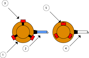
3 Point Grippers
3 point or three finger grippers are often used to self-center a misaligned part for pick up.
In the graphic below we are looking down at the gripper, and the fingers, seen from the top, are red.
- Depicts the gripper body
- Shows the supply line is charged
- The gripper fingers are opened to their widest
- The supply line is now opened to exhaust
- The fingers have moved to their closed position

The finger stroke in a 3 point gripper is fairly limited, but it can be magnified by the tooling that’s attached to the fingers.
As in most forms of commercially manufactured grippers, the 3 point gripper can accept proprietary proximity switches to help identify the tooling, and by extension the parts position.
In order to help prevent internal impact of piston on end cap damage gripper operation should be controlled by flow controls whenever possible, this to attenuate speed to reduce metal to metal force. Flow controls can also soften the impact of the gripper fingers and tooling on the part to be picked.
